
Page 448 - CATALOG
P. 448
RANGER TELESCOPING SLIDING GATE ACCESSORIES
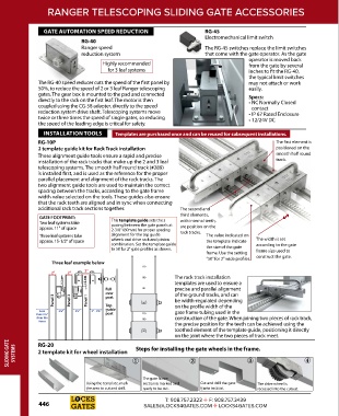
GATE AUTOMATION SPEED REDUCTION RG-45
Electromechanical limit switch
RG-40
Ranger speed The RG-45 switches replace the limit switches
reduction system that come with the gate operator. As the gate
operator is moved back
Highly recommended from the gate by several
for 3 leaf systems inches to fit the RG-40,
the typical limit switches
The RG-40 speed reducer cuts the speed of the first panel by may not attach or work
50%, to reduce the speed of 2 or 3 leaf Ranger telescoping easily.
gates. The gear box is mounted to the pad and connected Specs:
directly to the rack on the first leaf. The motor is then • NC Normally Closed
coupled using the CG-58 adapter, directly to the speed contact
reduction system drive shaft. Telescoping systems move • IP 67 Rated Enclosure
twice or three times the speed of single gates, so reducing • 12/24V DC
the speed of the leading edge is critical for safety.
INSTALLATION TOOLS Templates are purchased once and can be reused for subsequent installations.
RG-10P The first element is
2 template guide kit for Rack Track installation positioned on the
These alignment guide tools ensure a rapid and precise smooth half round
installation of the rack tracks that make up the 2 and 3 leaf track.
telescoping systems. The smooth half round track (#289)
is installed first, and is used as the reference for the proper
parallel placement and alignment of the rack tracks. The
two alignment guide tools are used to maintain the correct
spacing between the tracks, according to the gate frame
width value selected on the tools. These guides also ensure
that the rack teeth are aligned and in sync when connecting
additional rack track sections together. The second and
third elements,
GATE FOOTPRINT:
Two leaf systems take This template guide sets the s with internal teeth,
pacing between the gate panels at
approx. 11" of space 2-3/8" (60mm) for proper spacing are position on the
Three leaf systems take alignment for the top guide rack tracks. The value indicated on
approx. 15-1/2" of space wheels and drive rack and pinion the template indicate The width is set
combination. Set the template guide according to the gate
to 50 for 2" gate profiles as shown. the size of the gate frame size used to
frame. Use the setting
“50” for 2" wide profiles. construct the gate.
Three leaf example below
120
2" 2" 2"
1-2 mm 1-2 mm 100 The rack track installation
templates are used to ensure a
Fall 80 precise and parallel alignment
over of the ground tracks, and can
Panel 3 Panel 2 Panel 1 Top 50 be width-regulated depending
post
gate frame tubing used in the
Less 2⅜" 2⅜" 3" - 3⅜" guide on the profile width of the
than 2¼" post 120
from the 100 construction of the gate. When joining two pieces of rack track,
fence
the precise position for the teeth can be achieved using the
toothed element of the template guide, positioning it directly
50
on the joint where the two pieces of track meet.
SLIDING GATE SYSTEMS RG-20 ① ② ③ ④
Steps for installing the gate wheels in the frame.
2 template kit for wheel installation
The gate frame
Using the template, mark section is marked and Cut and drill the gate The drive wheel is
the area to cut and drill. ready to be cut. frame section. recessed into the cutout.
T: 908.757.2323 ✛ F: 908.757.3439
446 SALES@LOCKS4GATES.COM ✛ LOCKS4GATES.COM