|
|
|
|
|
|
|
Do you want to be a better CNC'er in 37 Seconds? Get Better Tool Life, Surface Finish, and Material Removal Rates Fast. It's that easy. You can install and get results now. |
2010 CNC Blog Archive
7/27/10
An iPad Mach3 Pendant
This is pretty cool.
How would you like to use it as a full-featured Mach3 pendant and even run G-Wizard too so you can check your feeds and speeds or do a quick calculation right at the machine? All this when neither Mach3 nor G-Wizard can be run on the iPad. What gives? Or, how would you like to make a quick tweak to your CAM program, but it's on a machine in another room from where your PC is located? Tweak and fire up the DNC right from your iPad.
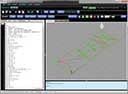
Find out how to do it here, and you'll soon be able to do this:

The New Mach Standard Mill screen set running on my iPad...
More testing needed, but for circa $12, this is pretty cool. A lot of folks don't like to run the Internet on their Mach3 machine. They want to keep the machine lean and mean and dedicated to Mach3 so there are no hiccups. Here's your chance to access the Internet, G-Wizard (which wants an Internet connection), and get a fancy new pendant all at the same time.
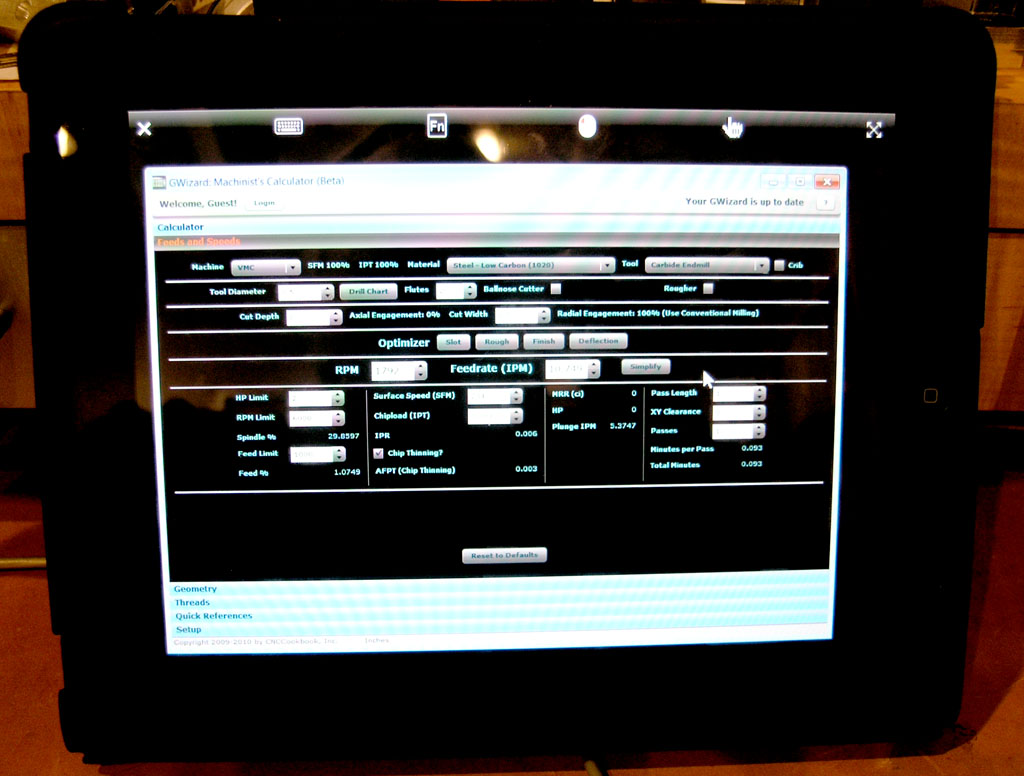
G-Wizard works great on the iPad this way...
7/25/10
The Fascinating World of Dry (and Near Dry) Machining
For many machinists its hard to imagine life without flood coolant. For others, its a necessity because their machine may not be set up for flood, or there may be other factors at work. Many sources indicate that coolant related costs are much higher than tooling--2 to 3x as much in fact. In addition, we live in a world that is increasingly concerned with the environmental and health impacts of what we're doing. Disposing of old coolant is problematic for most shops, and breathing in too much coolant mist is a huge potential health risk. Shops in Europe, for example, already much more commonly use Dry or MQL (Minimum Quantity Lubricant) Machining Techniques than in the US because coolant disposal costs are much higher there. Yet, countries like Germany are still forces to be reckoned with in terms of their manufacturing economies. There are new regulations already proposed that over time would make it harder to keep on with flood cooling here too.
Enter the world of Dry Machining. Can we machine without flood coolant? In many cases, the answer is, "Yes!" But what does it entail?
First, recognize that coolant is performing a number of tasks:
- Cooling: That's why the call it coolant!
- Lubrication: So gummy materials like aluminum don't create built up edge, and to reduce friction, and therefore heat.
- Chip Clearing: In many ways, this can be the most important function of all. Recutting chips destroys surface finish and dulls tools much more quickly. In the worst case, a cutter down in a slot or hole can get clogged with chips and get much hotter or even break.
When Dry Machining, we have to consider each of the functions of the coolant we hope to get rid of.
Lubrication and Built Up Edge
Let's start with Lubrication. I have the least to say about it, but that doesn't mean it isn't important. For starters, lubrication helps the tool to cut more easily and while generating less heat. As the face of the tool slides across the workpiece, it rubs while cutting. As the chip curls up, it also rubs on the tool, generating more heat. All that rubbing will produce less heat with a little lube, just like any sliding fit would. That's an important role for lubrication, but it's kind of a refinement of the cooling issue (generate less heat by reducing friction and we don't have as much to cool). A much bigger deal is reducing the likelihood of Built Up Edge (BUE). This is a big deal as anyone who has seen a big wad of aluminum get welded to their cutter will attest to. Things stop working pretty quickly when that happens!
Fortunately, BUE is pretty material-specific, and mostly applies to Aluminum and Steel that lacks much carbon or other alloying substances. Use of really sharp cutters with very high rake angles (positive rake is your friend!) also help tremendously. In the end, a little bit of mist can deal with this problem as well as flood coolant, so it isn't the end of the world. Just don't forget to do something before that wad of aluminum welds itself in all the wrong places.
Chip Clearing
Next up is my personal fave to worry about when Dry Machining: Chip Clearing. A good air blast can help tremendously with that. But, certain operations, typically hole making, have a hard time getting by on air alone. Deep hole boring and drilling are going to be the two operations you'll have the most trouble going dry on for that reason. If you must, at the very least try to offset the lack of flood with through tool air and preferably through tool mist. The trick is pumping enough of it through to blow the chips out. It's easier with a liquid coolant because it is denser, and less of it will carry the chips away better, not to mention conducting heat better. If you get it all right, with through tool mist, you can even see longer tool life than with flood coolant. Note that the natural chip clearing advantage gravity gives to horizontal mills and lathes versus vertical mills is particularly helpful if you're making holes without flood coolant.
Cooling
Which brings us to our next issue, Cooling. The temperature of the tool is probably the biggest factor affecting too life. A little heat is good, as it softens the work material, making it easier to cut. A lot of heat is bad, as it softens the tool, which means it wears rapidly. Note that the heat to be tolerated is hugely dependant on the tool material and coating. Carbide takes a lot higher temperatures than HSS. Some coatings, such as TiAlN really need the higher temperatures to do their job properly, and are often used without coolant. There are lots of stories out there where turning the coolant off increased tool life under the right conditions. Carbide is susceptible to micro-cracking under the thermal shocks of uneven heating and cooling. Sandvik, in their cutting tool study course, recommend either no coolant or copious amounts of coolant to avoid this problem. It should also be note that too much heat is not helpful to accuracy, as it makes your workpiece change size.
How, then, can we keep things cool without flood? Before we get into that, a word about coolant type. There are water soluble coolants, and there are oil-based coolants. From a cooling standpoint, the water soluble coolants win. How much? Consider this data:
Coolant |
Specific Heat of Coolant |
Steel A (tempered) Temp Decrease % |
Steel B (annealed) Temp Decrease % |
Air |
0.25 |
||
Compound oil, low viscosity |
0.489 |
3.9 |
4.7 |
Compound oil, low viscosity |
0.556 |
6 |
6 |
Aqueous solution of wetting agent |
0.872 |
14.8 |
8.4 |
Aqueous "soda product" solution, 4% |
0.923 |
- |
13 |
Water |
1.00 |
19 |
15 |
First thing to notice about the table, is that the efficiency of the various coolants at removing heat directly corresponds to the specific heat of the coolant. Second thing to notice is that air is pretty lousy, about 1/4 as good as water. It's interesting to note that the oil-based coolants are about half as effective as water-based in terms of their ability to cool the tool and workpiece. Between that and the health considerations, its no wonder a lot of shops have gone to water-soluble coolants--they just cool better. One last think about flood coolants--above a certain critical surface speed, they all start to work about the same, and the faster you go the less cooling effect they have. One reason for this is that when things are going really fast, there isn't time for a big gout of coolant to make it's way into all the nooks and crannies. Cooling becomes less and less consistent, and this also contributes to the shock cooling effects that make coolant hard on carbide life above certain speeds.
Well, putting aside that we may be using TiAlN coatings or other conditions that don't want the coolant, we're still not at a loss. Plain old air provides cooling, but, it'll take quite a bit of it to keep up with the cooling we had from flood. So, make sure you have plenty available. Mists also cool better than dry air, and can rapidly close the gap with flood where cooling is concerned. A mist also gives us the opportunity to reintroduce some lubrication, which is very helpful with materials like aluminum. Here's another of life's ironies--at higher speeds, mist does a better job getting into the nooks and crannies than flood coolant can.
There is another answer, though, which is to use air that's already cold. You certainly can refrigerate the air in various ways, and it cools all by itself as it expands coming out the nozzle, but, there is a nifty device called a Vortex Tube that will cool the air too. The coolant data above, as well as a detailed study of cooling using plain air or a Vortex Tube may be found in Brian Boswell's fascinating PhD thesis, "Use of air cooling and its effectiveness in dry machining processes."
This is quite a fascinating read, if you really want the nitty gritty. Boswell goes through rigging up some fascinating lathe toolholders that have air passages for directing air streams onto the insert and the workpiece in all the right places, but he ultimately concludes the Vortex tube is a better mousetrap. If you plan to use plain air, it has to be applied in just the right places to get the job done. Boswell found the Vortext Tube was much easier to adjust because its nozzle can be further from the workpiece, and that in the end, it was capable of keeping the workpiece just as cool as flood coolant.
That sounds very promising. As it happens, I've got a Vortex Tube set up for this purpose that I got cheaply on eBay. I had set it aside because they use quite a lot of air, but since installing the big compressor, I plan to bring it out and give it another try. One of the things I wonder about is using it from one side and a little mist from the other for cutting materials like aluminum that are prone to sticking to the cutter.
Cutting Parameters for Dry Machining
Okay, let's suppose you don't have anything as exotic as a Vortext Tube, but you're set up with air to blow the chips away, and perhaps some mist for lubrication. What impact does this have on your cutting conditions (feeds and speeds) versus flood coolant? Remember, I'm the G-Wizard guy, and wading through all sorts of PhD thesis and other information is what I do to put G-Wizard ahead of the pack. So, I've been gathering the data on this, and am ready to start building it into G-Wizard. Here are some preliminary results:
1. Leave the chipload alone. The parameter to adjust based on coolant is your surface speed, which will result in somewhat lower feedrates for a given chipload.
2. Above a certain surface speed, forget about adjusting for coolant. Most of the time you'll want to turn coolant off at this speed anyway. Let's call this the critical surface speed. It's a little lower, but one can assume that it is definitely the recommended speed for TiAlN coated tools. TiN coatings can still benefit from coolant, so the number is at the high end of the TiN ratings and definitely below TiAlN. Obviously this all varies by the material you're cutting, so I can't just trot out a number.
3. Below the critical surface speed, there is a correction factor that can be applied. Like the critical speed, the factor varies by material, but it ranges from a low of about 60% to a high of 85%. In other words, for some materials you should run at 60% of the recommended speeds (manufacturer's recommendations almost always assume coolant), and for others, you could run at 85%. The variations are a function of factors like how well the material conducts heat (high temp alloys are tough to machine in part because they don't conduct heat so well, so it builds up right at the cut), how much it relies on the lubricating properties of the coolant, and so on.
I'll post another article when I get done building coolant correction into G-Wizard, which won't be too long because after several months of research, I finally collated all the results today. Meanwhile, get signed up for the free Beta test (all it takes is name and email), and you'll hear about it directly:
![]()
What About Surface Finish?
There is one last Dry Machining issue to be shared. When finish machining, the surface finish of Dry Machining is often not as good as with Flood Coolant. There are many contributing factors, but a lot of it comes from the need to slow down the surface speed. When that happens, its important to compensate with a larger tool radius (or the milling equivalents) to keep the finish up. The secondary factor is the lubrication effect makes for less tearing and more gentle burrs. Mist can be helpful there.
Conclusion
All right, so what's the conclusion here?
Clearly, flood coolant is superior to dry machining and mists if we can ignore the costs associated with the coolant, and if we have a machine capable of dealing with flood coolant. But, the effects are perhaps not as extreme as some may have feared. Mist is recommended for sticky materials, a Vortext Tube or other cooled air solution can work just as well as flood at the cooling part, and, if all else fails, at least make sure you've got an air blast to clear the chips. Given all that, the difference between Dry and Flood Cooling is probably in the 20-25% range in terms of impact of Surface Speed and none at all on chiploads.
Some situations that are difficult without coolant:
- High-temp "Super Allows" pretty well must have coolants unless you use tooling where coolant isn't recommended.
- Materials that form a built up edge (some stainless and aluminum) want either coolant or at least mist to discourage it through lubrication.
- It's very hard to get the chips up out of deep holes without coolant. Through the tool high pressure mist is a possibility.
Now consider:
- If your spindle isn't the fastest in the land, you may have already detuned your surface speeds downward because your spindle won't go fast enough. This will largely be true with aluminum (or soft materials like brass) and smaller cutters with carbide. The net is no penalty for such machines for not having flood coolant.
- You can often pick up the lost feedrate and more using chip thinning. Try the G-Wizard calculator to see how that works or read my article on chip thinning.
Now, I can run plenty fast enough without flood, but I still want a darned enclosure on my mill to keep the chips inside and not all over the shop!
For more on Dry Machining, try these articles:
How it Works -- Dry and new-dry machining
The 10 commandments of dry high-speed machining
7/23/10
Mach3: What a Difference a Screen Makes
They say beauty is only skin deep, but where software is concerned, I think the UI runs much deeper than that. Without a great User Experience, an otherwise very powerful engine can lurk beneath unused.
I've been using Mach3 for years, and love it. It's a powerful engine, and it has had a decent UI, but not a great UI. By now you've probably seen it or even tried it:
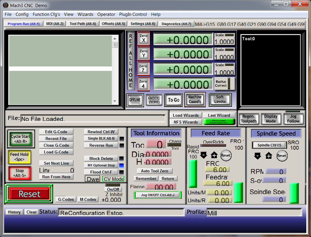
The Old Mach3 UI...
It's functional, but garish and things don't line up very well. There are deeper issues, but suffice it to say, I have been thankful that Mach3 allows alternate screens (just one more aspect of the powerful engine), and I've been taking advantage of it for quite a while. Tormach provides an alternate screen that's pretty and more functional to their users too. It's written in Flash and deals with utilizing more screen resolution where available.
This is all fine and well, but unless Tormach or someone deals with setting up a turnkey system for you, many users will not go to the trouble of modifying or even changing their screen set for Mach3. But, there is good news--Brian Barker and David Bagby are making available for Beta test a new Mach3 screen set that's excellent:

Isn't that a gorgeous screen? Much calmer, though no less complex. Because of the tasteful use of colors, and all the elements are properly aligned, they eye is less distracted by little imperfections and can focus on the task at hand. There's a lot more to this screen set than just good looks, though. Dave Bagby invested a lot of time analyzing other popular Mach3 screen sets and talking to users about their likes and dislikes, and he built a whole lot of that into this screen set.
Let's start with consistent navigation. The bar along the bottom lists all the available screens. And it stays put--no matter which screen you're on, the bar is in exactly the same place with exactly the same choices. But that's not all. If we look at the "User Exts" screen, a place for you to put any extensions you've made to Mach3, you can see that the jogging and MDI clusters stay put as well:
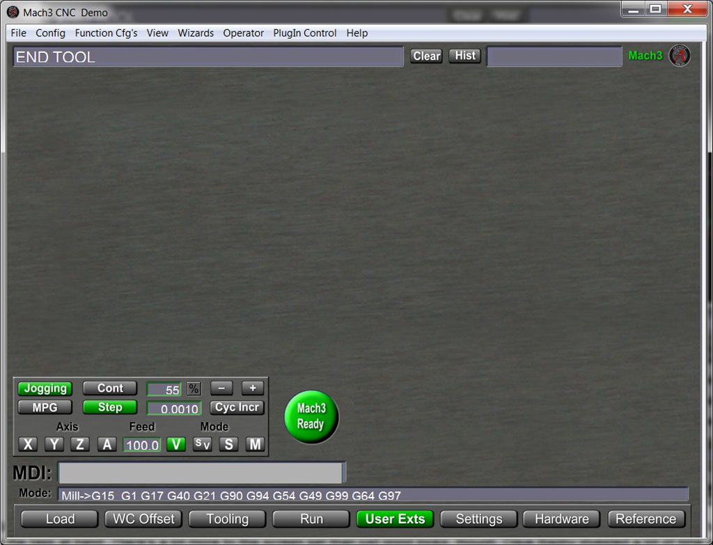
There's a lot going on in a CNC controller, and some of the screens you won't visit all that often. Always having the nav controls (your most commonly used controls) in one place is hugely valuable to productivity. Note that the status information is right at the top and pretty well stays there too unless you're on a screen where it would make no sense. Consistency is a real virtue for User Interface (or User Experience as it has come to be known) design.
I want to point out one more goodie, which is the ability to get at all the documentation, release notes, and reference material right from your Mach3 screen:
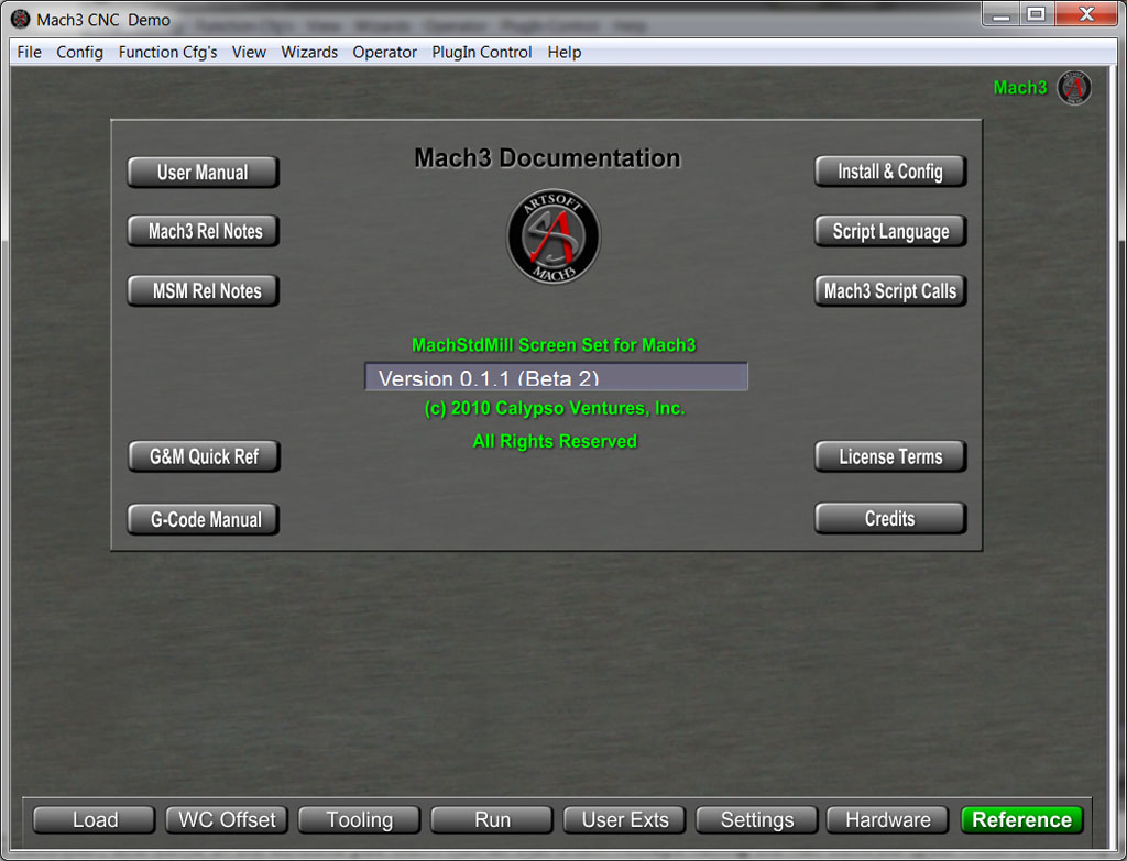
It's very handy not to have to go dig up a printed document or fumble for a pdf or web browser. There's a lot more to like about this screen set. I think it'll be great that every Mach3 user can get it by default when they go to the new version. That saves them the vagaries of learning how to install a new screen set (although Dave has built a nice installer program to go with these new screens as well). I've found the Mach3 Standard Mill (the name of the screen set) to be quite stable and a wonderful improvement over the defaults. Highly recommended.
The full scoop on how to get the new screen is here on the new support forum for the screen set. Be sure to go through the instruction before just installing. The screen was an integrated effort with Mach3, meaning there is some new Mach3 functionality needed for it to work properly. As a result, you'll need to download a new version of Mach3 (still a beta test) to use the new screen set. I was part of the alpha test for the screen set, and have really enjoyed it. Dave is wonderful about trying to make the code as stable as possible, and especially about providing lots of great documentation.
BTW, for those of you who are into software (sorry, I am, ignore if you aren't) and want to know what makes it all tick, there are several threads full of fascinating info about what MSM (Mach Std Mill) does under the covers and how it is integrated with Mach3. As Dave Bagby says more than once, "this is not your father's screen set." Many screen sets are just pretty pixels with a few added macros here and there. MSM truly is an integrated effort with Mach3 that significantly extends the functionality. There are some tantalizing details of that in this thread, which responds to why one must install a new Mach3.
7/17/10
Boring Big Holes With Small Boring Heads
Sometimes we need to bore a large diameter, but we only have a small boring head and it isn't practical to put the part in the lathe. What to do?
I like these ideas from Practical Machinist:
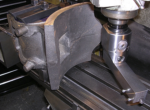
Check out the big bar. It's rigged across a couple of the holes, I'll bet...
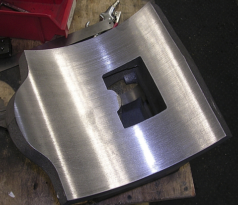
Take it easy, light cuts, and the surface finish looks pretty decent. This was done on a Bridgeport. Initial passes with quill, final pass with quill locked by cranking the knee...
Increasing the Rigidity of a Small Lathe
The compound slide on a lathe is convenient to have, but it does reduce rigidity a certain amount. For that reason, you'll often see cases where the compound is removed and the tool is mounted directly on the cross slide. But I came across this clever method of increasing rigidity for a small lathe:
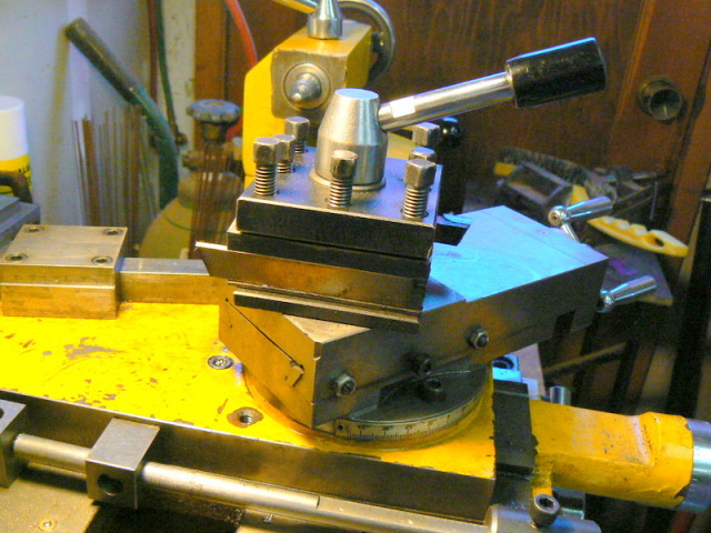
A typical compound slide arrangement...
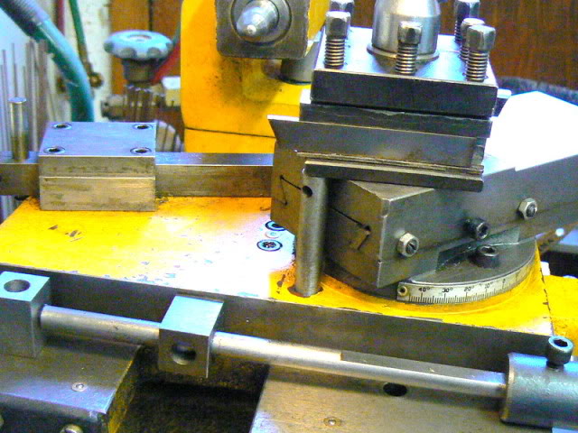
Compound supported by a screw in post to reduce deflection. I'll bet that helps quite a bit for a parting off tool such as is shown...
Anything Worth Doing is Worth Overdoing: Making a Boeing 737 in the Garage
Okay, the title does exaggerate, but this project deserves a little exaggeration. What starts out as lowly particle board eventually becomes an amazing replica of a 737's center console to be used with a flight simulator:
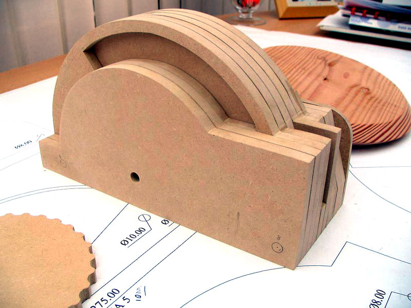
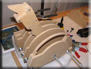
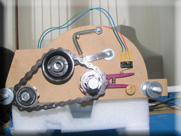
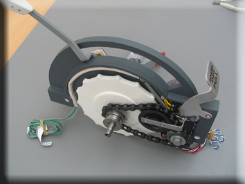
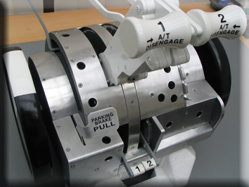
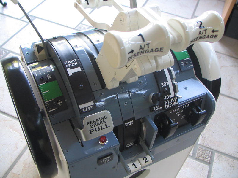
How real does it need to be?

This one is the real thing...
7/7/10
How Can I Increase My Tool Life?
I see this question fairly commonly. Let's assume you're doing everything "right"--correct speeds and feeds, no chatter, good clearance so you're not recutting chips. That's an important baseline. Once you get there, suppose you still want to increase your tool life. The usual answer, based on Taylor's equation for tool life, is to reduce your SFM. Surface Speed (largely spindle rpm), is the major determinant of tool life, while chipload and depth of cut are much less significant.
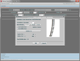
Based on a discussion of this on the HSM board, I recently added the ability to calculate how much a reduction (or increase) in your SFM will impact your tool life. G-Wizard has long had the ability to apply an override or correction factor to its recommended SFM. The correction factor can be stored with a machine profile. The new calculation looks like this:
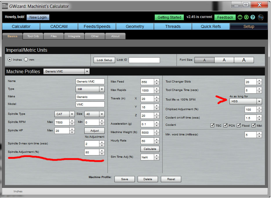
Scan down to where it says, "Tool life vs 100% SFM". Reducing SFM 20% gets you 6x longer tool life!
As you can see, a little reduction in you SFM can dramatically add to tool life. In the example screen shot, I am reducing SFM to 80% of recommended, so it runs 20% more slowly. The predicted increase in tool life is 6x.
As I write this I haven't yet released the update to G-Wizard for tool life in the wild, but it'll be out in the next release I make.
7/5/10
Slick Tormach Toolchanger Video
One thing about Tormach: those guys are never sitting still! I came across this video of their toolchanger prototype and thought it was very cool:
A lot of folks are going to want to get their hands on that Bad Boy when Tormach finishes making it production-worthy. They showed a prototype in the past, but it looks like this one is making some real progress forward. Adding a toolchanger will really step up the capability of the Tormach mill. This is one I'll be watching closely.
7/3/10
BC: Before CNC at NACA/NASA
Thanks to an HSM thread, I went out and found some cool pictures of how hydraulic tracer mills could be used with a 4th axis to make complex parts. Yes Virginia, there was life BC (Before CNC)!

The date: 1945. Cutting an impellor for a turbocharger or centrifigul flow turbojet. Twin hydraulic tracing probes, larger than life tracing models, 4th axis, and a Bridgeport headed mounted on that Cinci milling machine so they can get more rpms.
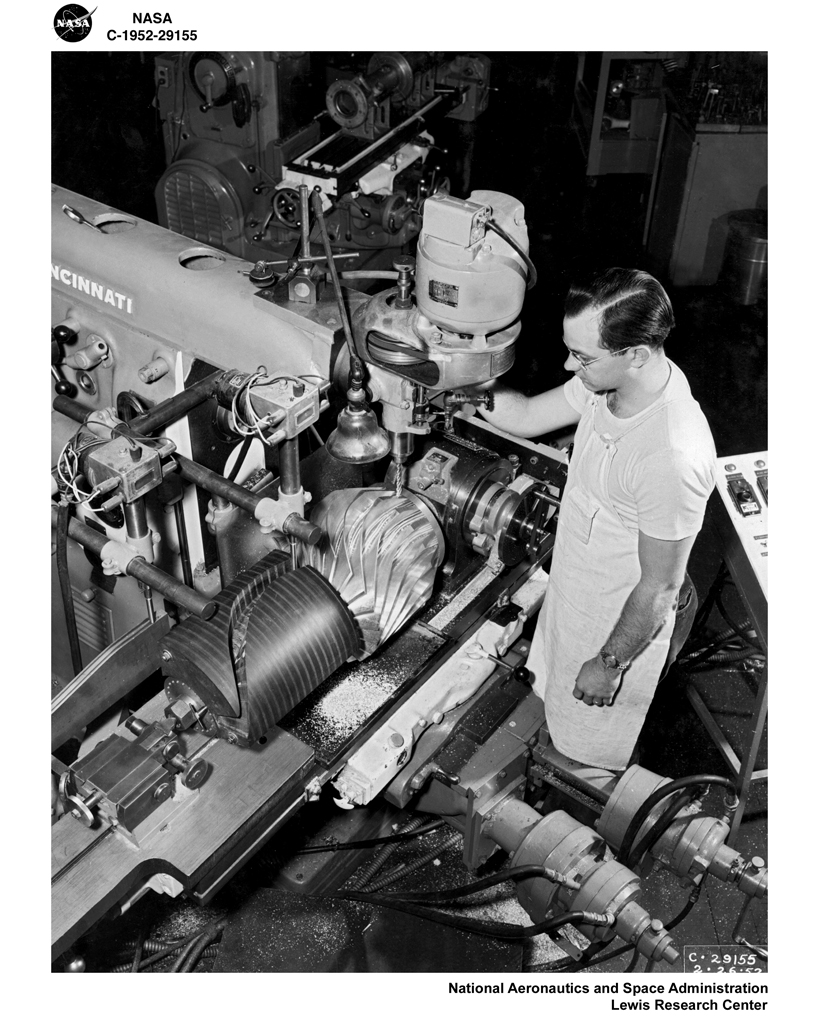
1952. Could be the same machine, just a little bit older and with a few more modifications. That's a more complex looking impellor. The machinist has a T-shirt and jeans. He'd feel right at home in a shop today! Note the one tracer model is on the 4th axis, so it drives the A-axis. The Z-axis is controlled by the model that is just off the picture on the left. The models look like they're made from plywood?

Making 4 simultaneous blades for a jet engine with a tracing mill...

Boring on a jet engine section. Note the shopmade steady rest under the flange. Just a couple of bearings to support the bottom. That's a good sized boring bar he has there. Come to think of it, the compound on that lathe is nearly as big as my lathe!
7/2/10
Free Local Advertising for Your Business on Google
A lot of machine shops rely on local business. It turns out you can get some free advertising help from Google. They're trying to make Google Local and Google Maps more relevant, and they want your information to help. In exchange, you can wind up with some free advertising. To take advantage of it, you'll need:
- A description of your business.
- Your phone number, address, and any other contact information
- A logo or image you use with your business
- A coupon or special. This is optional, but Google will let you add one for free if you like.
To get hooked up, follow these steps:
1. Go to Google Local and search for your business. You need to verify it is not yet listed with an ad.
2. Go back to the Google Local link and click Add/Edit Your Business (bottom left part of the page).
3. Follow the steps provided by Google.
You can check back in a few weeks to verify what got listed.
This idea comes from the Hubspot blog, which is a great source of online marketing ideas for small businesses.
6/30/10
Pre-CNC Machine Tool Automation
Screw machines are fascinating devices. Programming is entirely mechanical. Here's a venerable Brown and Sharpe 2G chugging away:
Machine Vintage: 1942!
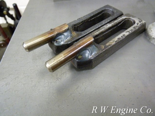
Handy Table Clamps from Pipe
These clamps from J Tiers look handy and very easy to make:
6/25/10
ShopVac Parts Catcher for a CNC Lathe
Watching that video made me think an excellent parts catcher for small parts could be put together from a shop vac for CNC lathes. Whether you choose to move the hose or leave it fixed near the chuck, it should be possible to control the vac with a relay and an M-code. Might want to put some foam rubber in the bottom of the shop vac barrel so the parts don't fall down too far and get banged up.
Worried About Viruses on Your Computers?
Some machinists will not let the machines in their shops have Internet access because they're worried about viruses. It's important to be vigilant, but it's also important to be well-informed and to run appropriate anti-virus software. I couldn't do without Internet access in the shop--too many great resources I want to refer to.
Some things to think about that I practice as well as some from a recent article I came across:
- Maybe you don't want to run one of the market leading anti-virus programs. After all, those are the ones most virus writers will try to get around first. Symantec and McAfee score pretty poorly in the article I linked to, for example.
- Viruses are much more likely to come to you via e-mail than web browsing according to the article. What are you doing to prevent it? I run all my email through Google G-mail. Google is a company that does a great job blocking spam as well as detecting and eliminating viruses from incoming messages. Plus, its much easier to use than Outlook, and I can access my mail from any computer with a web browser.
- Given that viruses are often passed around via email, what are your family members doing about virus protection? Be sure their machines are protected and that they understand not to click on any phishing notices. I hear from a lot of folks who were infected because a family member read an email from a friend that was infected and forwarded it. Of course, if your whole family is on G-mail, that helps too!
- Keep your software up to date. For example, if you use G-Wizard, there's a new 10.1 Flash player out that fixes various vulnerabilities and runs faster to boot. I always take the latest updates for my web browser, operating system, Flash player, and so on.
Just a few thoughts to stay safe in the online world!
6/23/10
Wonderful Amateur Machinist's Board
I wanted to give a hat tip to Mad Modder, which is a wonderful board. I had seen it before, but hadn't really got into the habit of checking in as often as I should. I think of it as sort of an offshoot of the HMEM Board, but one with a more general focus than just the model engines. Same really nice atmosphere (no trolls allowed), and as a result, many of the same really nice machinists that you meet around many other boards congregate here.
Here is a little sampling of some projects that caught my eye this most recent visit:
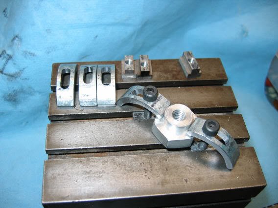
Talented machinist Rob Wilson's "Pin Clamps" (my made up name)...
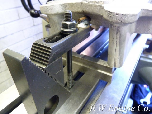
It's so cool to be able to make castings!
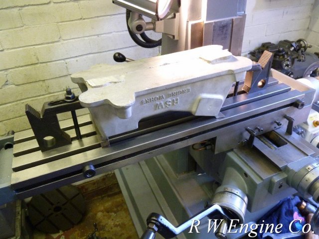
Why a pin clamp? Because now he can facemill the bottom of the casting without the clamps being in the way...
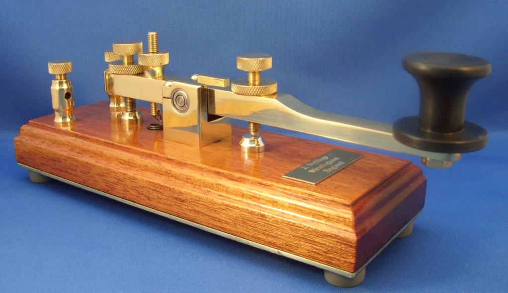
John from the UK's absolutely gorgeous Morse key
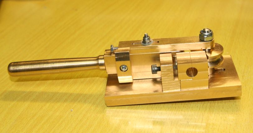
Nice brass tubing bender for small tubing ala G. Britnell's. Gotta make one of these some day!
Wander over and check out the site. You really can't go wrong if you like such projects!
6/20/10
Shiny Cubes
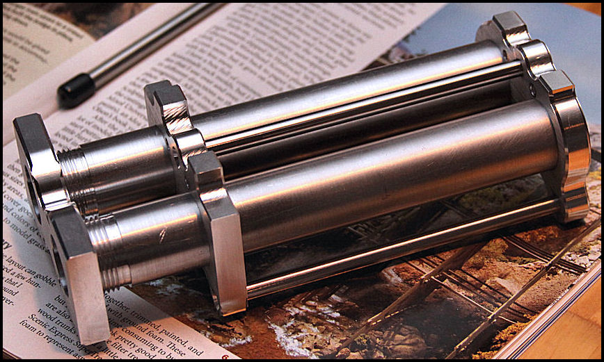
Here are some photos of some little (0.600") cubes I made. Eventually, they will be turned into some jewelry for my wife and daughter:
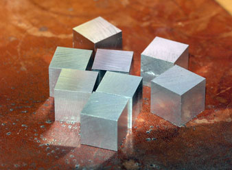
Actual size...

Close-up
These were done with my Glacern 45 degree facemill. They're 6061. Feedrate was 20 IPM, spindle was 1600 rpm, and depth of cut was about 10 thousandths for the last pass. It's hard to photograph, but there is a slight "rainbow" diffraction effect when the grooves are close together. You can see it slightly on one of the lefthand cubes (diagonally up to the left from the bottom-most cube). These would have come out better with full flood coolant (I don't have it), but they're not too bad considering they are straight off the mill. I'm going to throw them into the vibratory polisher for a few days before I get on with the next step. You can see a pretty good reflection in the one on the right, but as I've said before, you don't really get optical mirrors right off the mill.
6/13/10
Kenneth Maxon's Crazy Cool 'Bots
Amateur robotics is a decidely high-brow hobby, although I like to think that my CNC conversions are just "blue collar" bots.
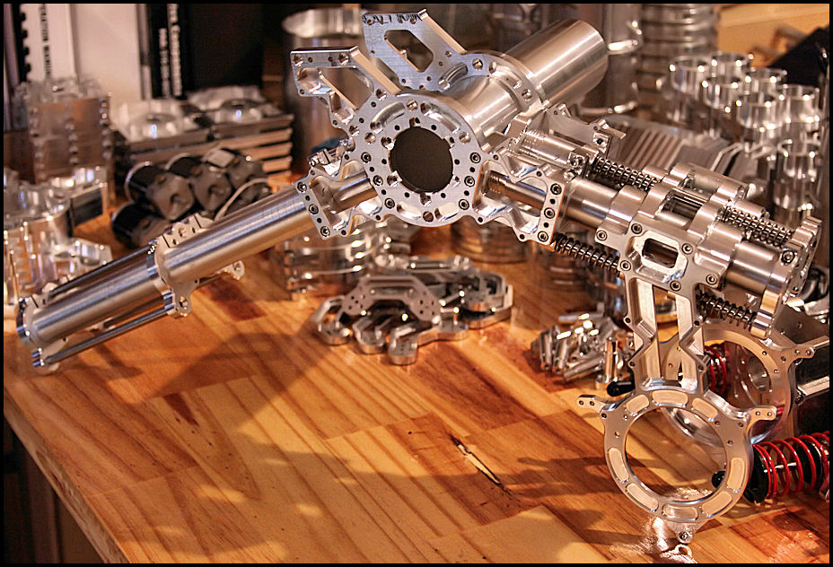
I've been following Kenneth's work for quite a while and he recently sent me some photos of a new project:
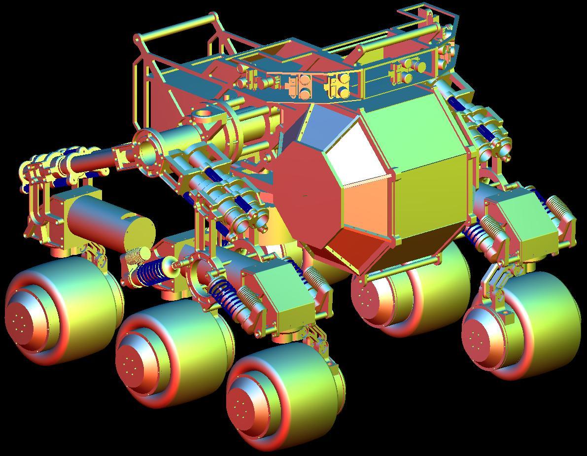
Sojourner's task is to autonomously circumnavigate a residential neighborhood...
One of the things I find intriguing about Kenneth's work is it is always so intricate. These are not simple, knock-it-together designs. The parts are quite complex and finely detailed:
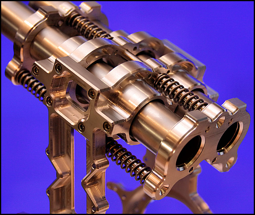
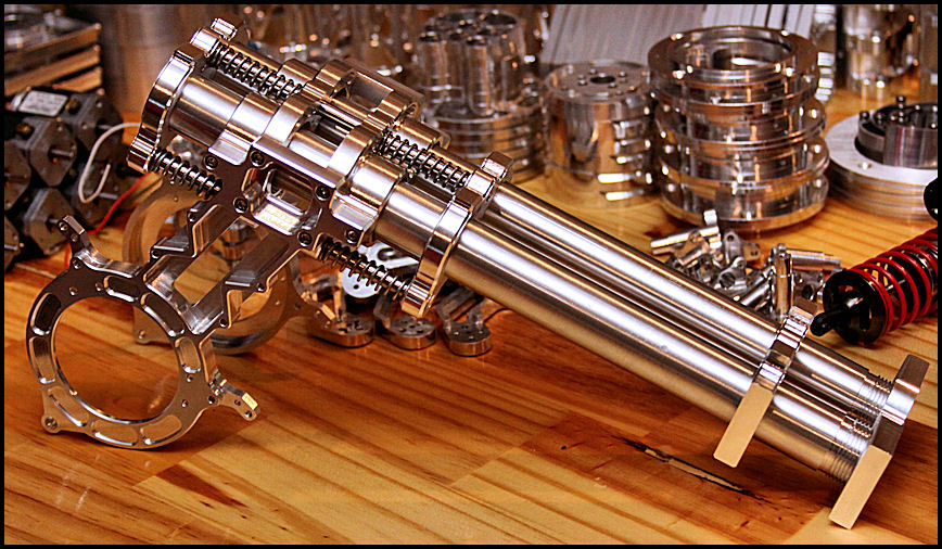
Be sure to head over to Kenneth's site, "Max's Little Robot Shop," for more!
6/6/10
Laser Fishmouthing (or Tube Scallops, if you prefer)
Michael Moore called my attention to this great video:
Looks like a great advertisement for why I need a plasma table with 4th axis to me! That laser really cooks, doesn't it?
Mill Fine Tramming Adjustment
Hold the presses, somehow I missed a really cool and very simple mod to the mill.I love this idea that MachineChick published on CNCZone:
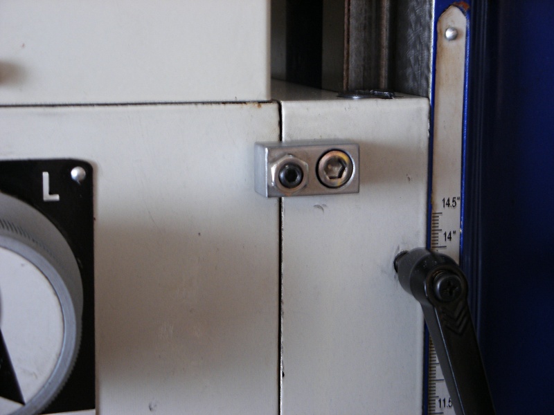
That little setscrew with locknut will apply pressure to the top of the head causing it to pivot smoothly. Makes tramming the head faster, easier, and more precise. I would think it might help hold the head in place a little better too! Mount one on either side so the head can be pushed either way.
This is now at the top of my projects page (not that they're really in order). I gotta get me one of those!
How Well Must I Align My DRO?
When you mount a DRO, every effort should be made to ensure the DRO is tracking parallel to the axis. A failure to do that can result in two problems:
First, the DRO is travelling the same distance as the axis, because it is not parallel. Hence there is some diagonal versus the shorter side of the triangle that the DRO reader head is moving.
Second, the potential exists for binding. The DRO's components are made to a high accuracy, and they don't like to have to "give" too much. The reader head is rigidly attached to the machine axis. If the scale itself isn't parallel to the axis, the reader head is going to be moving closer or further away from one end of travel to the other and could quite possibly be damaged.
Of the two, the second (potential for binding) consideration is by far the more important. The actual geometric error in measurement of a non-parallel scale is slight and be calculated using G-Wizard's triangle calculator as follows:
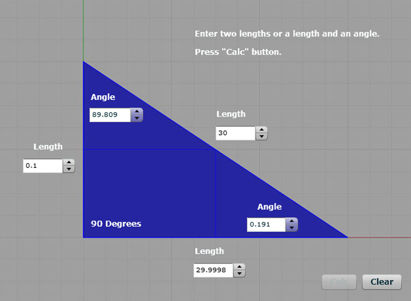
2 tenths error on a 30" DRO scale that is misaligned by 0.100"
Assume a scale length of 30" that is out of alignment by being high relative to the axis travel 0.100". When the DRO has travelled 30", the axis has only travelled 29.9998", so it's out by 2 tenths. Presumably, tenth accuracy therefore only requires alignment to 0.050" for a relatively long 30" scale. Even a long 60" Z-axis on a big lathe still only takes alignment to 0.025". But, most DRO manuals require you to align more much more closely.
There are some exceptions based on the construction of the DRO. Newall's excellent spherosyn DRO's use rods rather than glass scales. Once you have the head level to 0.002", there merely have you insert the rod and use a transfer punch to locate the mounting brackets. The head is only aligned so accurately because you have a relatively short baseline (length of the head) in which to determine that the rod is aligned with respect to the axis. However, the rod itself can tolerate a little "give" much better than a delicate glass scale.
Fishmouth Templates for Welders Using CAD
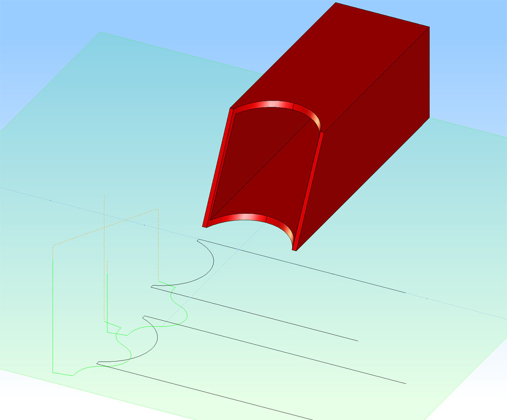
A fellow on HSM reading about the CNC fishmouthing mentioned his firm would create templates and then torch cut 6" pipe to make their fishmouths. He wanted to know if cheap CAD systems could make the templates by unrolling the surface. No problem. Rhino3D did that task lickety split:
In fact, I deleted a lot of the templates, because unroll gives you one for every exposed surface. There is an inner, outer, top front fishmouth edge, bottom front fishmouth edge, and even the ring that is the rear edge of the pipe. Print that out 1:1 and you've got your template.
6/5/10
CNC Fishmouths for Welders
CNC machines are excellent in terms of precision, repeatability, and doing tasks that would otherwise be difficult to get right manually. Take the cutting of arbitrary "fish mouths" as needed when welding tubing together to make frameworks. Imagine you're welding a bicycle frame, for example. Tubing of different sizes is coming together at various angles. The "fish mouth" is the shape one piece of tubing must have to be fit closely to the curve of another before welding can commence. Given the possibility of different angles, different diameters, and even different shapes (square tubing meets round tubing), these shapes can be odd. The name "fish mouth" (and I can't seem to decide if it is one word or two) comes from the shape's resemblance to a fish's mouth.
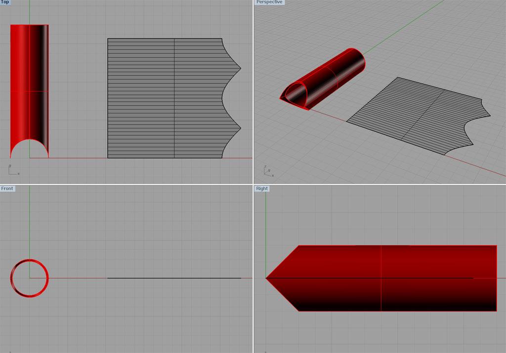
There are a variety of jigs and fixtures available to facilitate fishmouthing (if I may use that oddly contrived word). They hold the tubing in the desired configuration while an annular or other cutter comes down vertically. I didn't have such an apparatus at hand and needed to make some fishmouths as part of my tapping arm project. It seemed immediately obvious that my CNC mill would be a good choice for the job. The first task was to make up the proper curves for the fishmouths so my CAM program could generate g-code. That was also very easy in my favorite CAD program, Rhino3D. I started by drawing the configuration that needed the fishmouths:
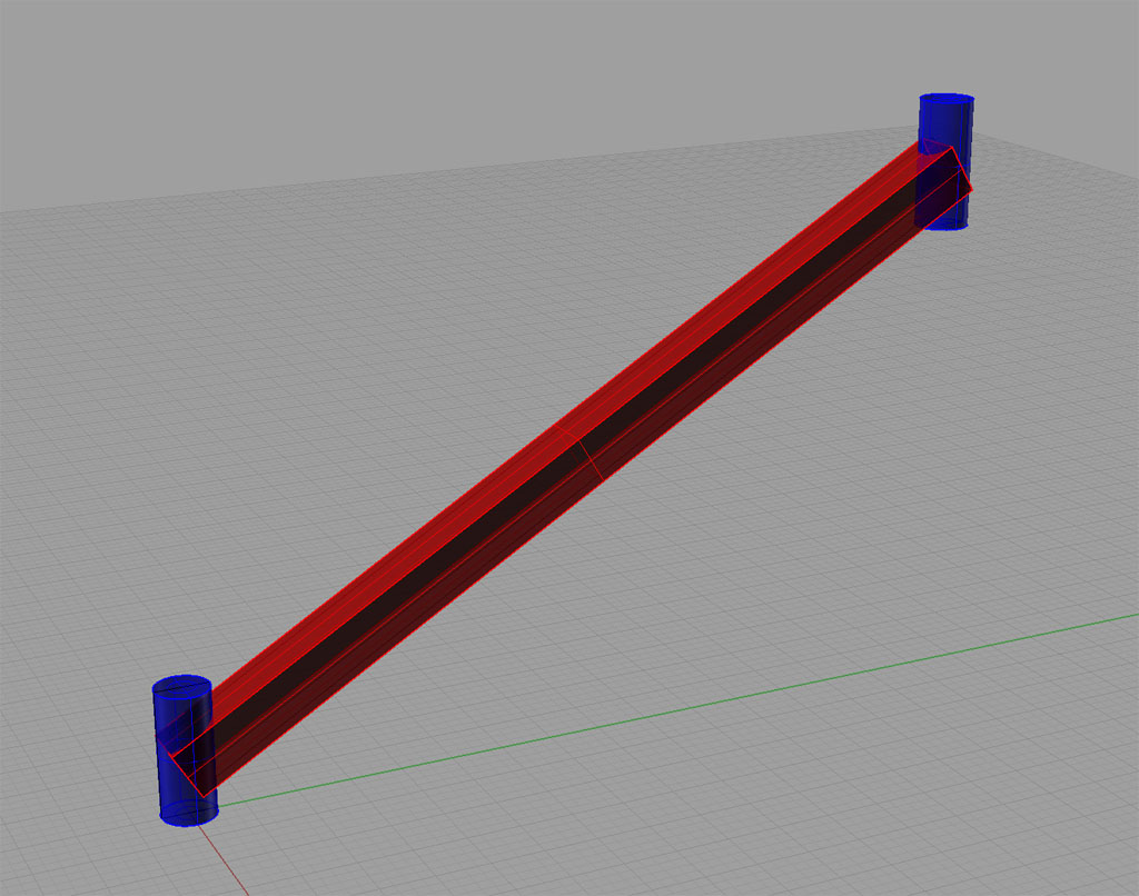
Two 1" diameter round pivot blocks with the 1" square tubing between them...
Since Rhino3D is a solid modeller, we can "subtract" shapes from one another. I merely drew up the configuration and then "subtracted" the two blue rounds from the red square tubing. What was left is a perfect solid model of the desired fishmouth:
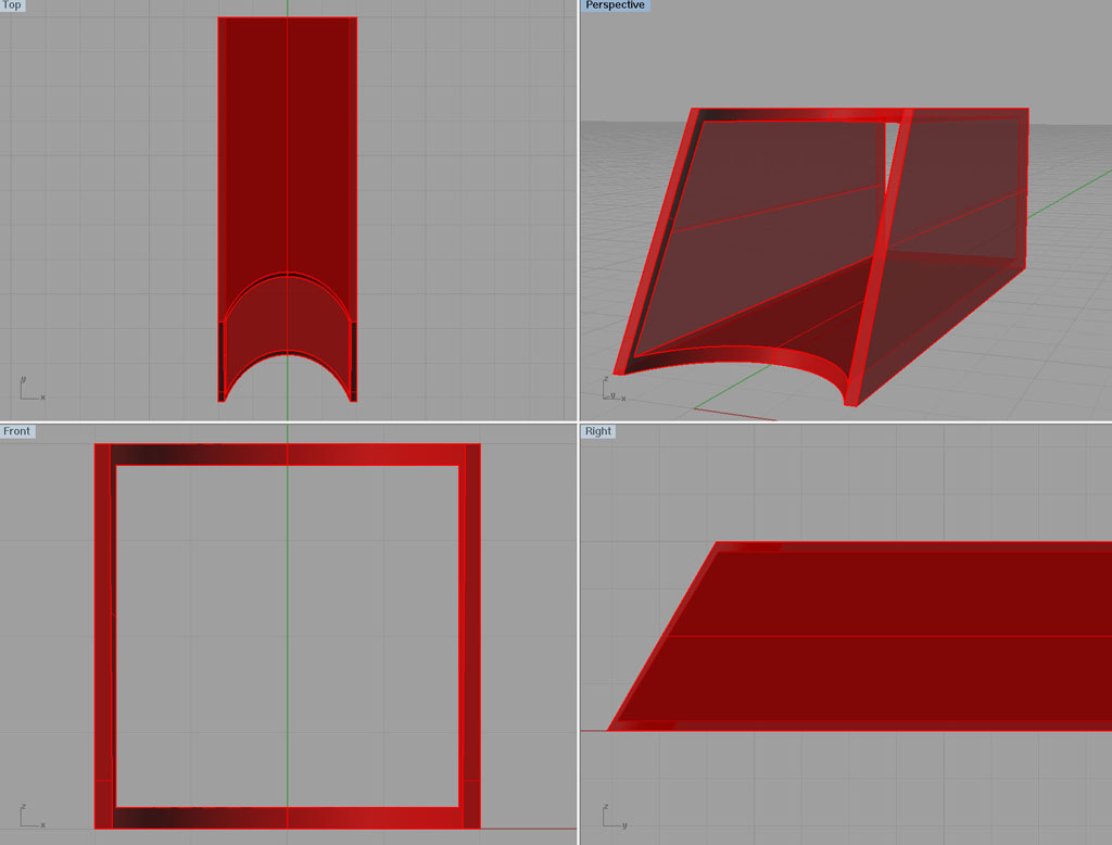
The result after "subtracting" the blocks to create the fish mouth with the right curves and angles...
Now I made 2 g-code programs using OneCNC. The first was to cut the diagonal side profile. "Why use CNC for something that simple?" you ask. Because its fast and easy. I have been fixturing using my Kurt-style vise. I set the part zero as being the left corner of the fixed rear jaw on the vise. I insert the square tubing 1" past that edge. Close enough is good enough--so even a tape measure will do on the diagonal. Insert tubing in vise, clamp, press green button, reverse tubing, repeat, done! CNC is great for this kind of repetition. Yes, you as easily set up a chop saw, but this was faster and more precise for me. In fact, I've seen a number of accounts of people using their CNC's largely just to saw pieces to size, especially lathes with bar feeds.
Okay, the second program cuts the upper and lower fishmouth. Its a quick and easy program. The curves are, in fact, elliptical and not circles, but that didn't phase OneCNC. Here's what the toolpath looks like:
Imported into OneCNC XR4 and profile curves created for the upper and lower curve...
The whole process took maybe one hour. If I'd had a fish-mouthing fixture, I could have done it faster, but probably not a lot faster. For this approach, I needed no special tooling and I can run off as many of these tubes as I like very quickly. The best news was not only that this was fast, but the fit was really nice. A little deburring with a file and I was ready to Tig together the parts.
6/3/10
Learning G-Code
G-Code is what the programs you feed to a CNC machine are called. While many prefer to avoid it as much as possible and rely on their CAM programs to "know" the g-code, you will ultimately come to a point where you wish you had a deep understanding of g-code. You will need such an understanding in order to do one or more of the following:
- Understand what your CAM program's g-code is really doing.
- Modify or fix that CAM program g-code to get a better result. I've seen bugs appear from time to time in every CAM program I've come across. If you don't know any g-code, you're just stuck with trial and error and at the mercy of your CAM provider. If you know some g-code, you can get into the CAM's program and fix the problem by hand in order to move ahead. Many have found that CAM generated code can also be improved upon with a little judicious hand tweaking.
- Lathe programs are often pretty simple and therefore not worth firing up the CAM program. Perhaps you don't even want to spend the money for lathe CAM.
- MDI. You're at the machine. Your CAM program is elsewhere. You don't have a drawing. You just want to make some chips quickly for a simple part, and the manual machinists are laughing at your inability to git 'er done. But wait! You've MDI and a notepad you can type code into. If you know g-code you can git 'er done.
The long and the short of all this is that a knowledge of g-code can be a very handy thing indeed. It's a skill that you add to your toolbox, and one that sets you apart from some of the other machinists who don't have it. If you're a one man shop, or even a small shop, it helps you to stand on your own two feet.
How best to go about learning some g-code?
Well that's what got me started writing this thing in the first place. At the moment, I am engaged in learning g-code at a deeper level than what most machinists would ever contemplate as even being useful. I know, that's a bold claim, but I don't make it lightly. There are three ways to learn about g-code. One is a warm up, and the other two are the real thing.
The warm-up is passive. Read books like Smid's bible on the subject, "CNC Programming Handbook." Read your machine or controller's documentation on g-code. Putting those two together, you are likely to start to feel some of the special pain I'm going through because as you will learn: g-code is not necessarily the same from one machine to the next. That's why CAM programs have Posts. The role of the post processor is to take what the CAM program produces and tailor it to your specific machine.
Read code too. Go over the code that you CAM program puts out and figure out what it is doing and why. You will discover, for example, that they all emit a ton of code at the beginning whose purpose is simply to put the machine into a known state so that every program starts out on the same page if you will. For example, OneCNC (my CAM program) throws out a line like this near the beginning:
N60 G0 G40 G49 G50 G80 G94
The G-Code Editor I'm writing as part of my G-Wizard software line has a special "Hints" capability that will translate that to English:
G-Code 0: Rapid positioning (moves at jog speed)
G-Code 40: Tool radius compensation off
G-Code 49: Tool offset compensation cancel
G-Code 50: Reset all scale factors to 1.0
G-Code 80: Cancel canned cycle
The "Hints" are to help people learn g-code faster. Are they helping you to understand what line N60 was all about? BTW, the editor isn't ready for public consumption yet, but if you want to be sure to be invited to try it, just join the G-Wizard Machinist's Calculator Beta Test so you'll be on the mailing list.
Okay, now let's say that you've looked at a fair bit of code, and you've now got some inkling of what those diabolical g-codes are doing inside your machine. Your next step is to write some g-code of your own. Try a simple program. Even if you're not going to cut any chips, load it into your control and single step through it while cutting "air" to see that it does what you expect. When you're comfortable with that, undertake a project that might be handy and something you'd use more than once.
For example, you could write a macro program that engraves your shop's logo at various sizes. In fact, you can even use your CAM program to create the logo (choose a 1" height so that its easy to scale it using G51 to any size you want and easy to calculate the scale factor (multiply by 1", Duh!). Use your new-found g-code programming skills to package that logo up as a reusable macro subroutine. Now you can slap it into any program, feed it a location and scale, and your logo will appear at the desired location and size. Cool beans!
So what's the last step in becoming a true Jedi g-coder? Well, in computer science, if you really want to learn a language inside and out, you have to recreate that language yourself. There is a lot of pain associated with that, but it is a rewarding experience in terms of the learning. If you happen to also need a g-code interpreter as I did for the G-Wizard Editor, then you have a happy coincidence. While it is hard to get good at writing g-code, there are a lot of times you can just bull your way through, trying various things until you get what you want. This is not the case when writing a g-code interpreter. The g-code interpreter has to understand anyone's g-code that happens to come in so it can do whatever it is going to do with the g-code--displaying a backplot of what your tool is doing in the case of my editor, or actually controlling that tool via steppers or servos in the case of Mach3 or a Fanuc controller.
Understanding anyone's g-code is where the rub comes in. The language itself seems simple, but it is not very well documented, and there are lots and lots of variations. I was taking note of all the reference sources I keep open when I'm researching how a particular g-code is supposed to work. Here is a partial list (perhaps you'll find some of it useful):
And of course, I have a couple of the Smid books and whatever else is available along with Google searches to find examples and more data. Some of it can be a bit obscure. Haas offers this PowerPoint slide show on some of their non-standard g-code behavior.
Do I really need to go through all of that stuff? Well, consider the G51 scaling code that you may want to use for your logo. First, there are a number of variations:
- X, Y, and Z may indicate the "scaling center" so that you can not only scale, but position relative to the original program.
- X, Y, and Z may instead indicate individual scale factors along each axis. X2Y1Z0.5 would make it twice as long in X, the same in Y, and half as long in Z, for example. Or, some controls put these individual factors in IJK.
- Some controls only allow one scale factor, to be contained in "P". P2 gives me an object twice the size while P0.5 is half the size.
You have to understand how the g-code interacts with the machine. For example, it may set or use some of the "#" variables that g-code programmers use. Many g-codes create modes that affect the behavior of other g-codes until the mode is cancelled. Certainly G51 scaling does that. You have to be cognizant that g-codes need not execute in the order the appear on the line. That's a bit mind boggling. There is a defined order in which the codes are executed, and that order is respected first, followed by the order on the line. This is a good thing. For example, we select the tool then we change the tool and not vice versa despite how it looks on the line.
There are other kinds of interactions too. G51 scaling does not affect tool path compensation (G40, 41, and 42). Depending on the control, it affects XYZ, IJK, and R.
And then there are the concepts associated with each g-code. For G51, the tricky concept is the "scaling center". To find the position of a scaled point, draw a line from the scaling center to the point in the program. That distance is what we apply the scale factor to. We then move the new scaled distance in exactly the same direction from the scaling center to find the newly scaled point. Sounds really complicated, and you have to get it right. Whereas if you are just writing the g-code, you can kind of eyeball the diagrams (if your doc has any) and try a couple of things until you get what you want.
There's useful hints and kinks to think about too. How about scaling by -1? Hmmm, that mirrors the program without "scaling" it at all. Clever!
I don't wish this business of learning g-code deeply enough to write your own g-code software on anyone, but I will tell you I'm enjoying it. For the rest of you, go learn some g-code. You may find you enjoy it quite a lot too!
3/3/10
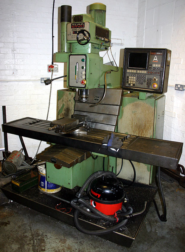
Rigging: Moving the Mountain to Mohammed
It's probably a personal limitation, but I absolutely dread rigging heavy machinery. It's really the logistics of getting it into place, and particularly off the truck. I have a home shop, it's up a hill, a big tractor rig can't come up, and I have no loading dock. Shippers all want to charge a fortune to provide a truck with a liftgate, and for many things you just can't get it done without a lot of finagling.
Recently, I saw a great solution, or at least a piece of the solution, while looking through some old posts on the PM boards. Instead of a loading dock, convert a scissor lift:
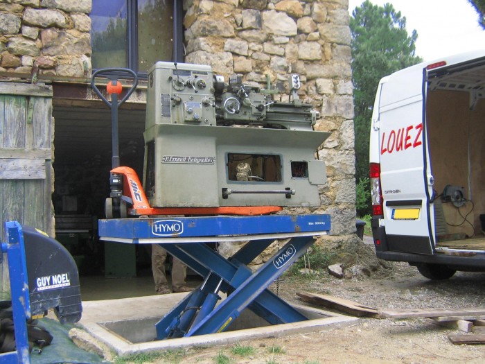
The scissor lift gets it off the truck, and the palette jack moves it into the shop. The lift has a 3 ton capacity. This is going to be much easier to get past the finance department (SWMBO) than a forklift!
2/15/10
Die "Traminator" and Spindle Squeegee
You must have noticed if you've read these pages for very long that I am a consumate gadget collector. A lot of machinists are in the camp of less is more. Why use a Blake Coax if you can just sweep your indicator? I'm in the camp of one more labor saving device that works is one less bit of labor. I need all the productivity help I can get in the shop!
I use the "Traminator" and my Spindle Squeegee for routine house keeping with the mill spindle. These are just a couple of handy gizmos whose jobs can be done with other more general tools, but that I like even so.
First, the spindle squeegee:
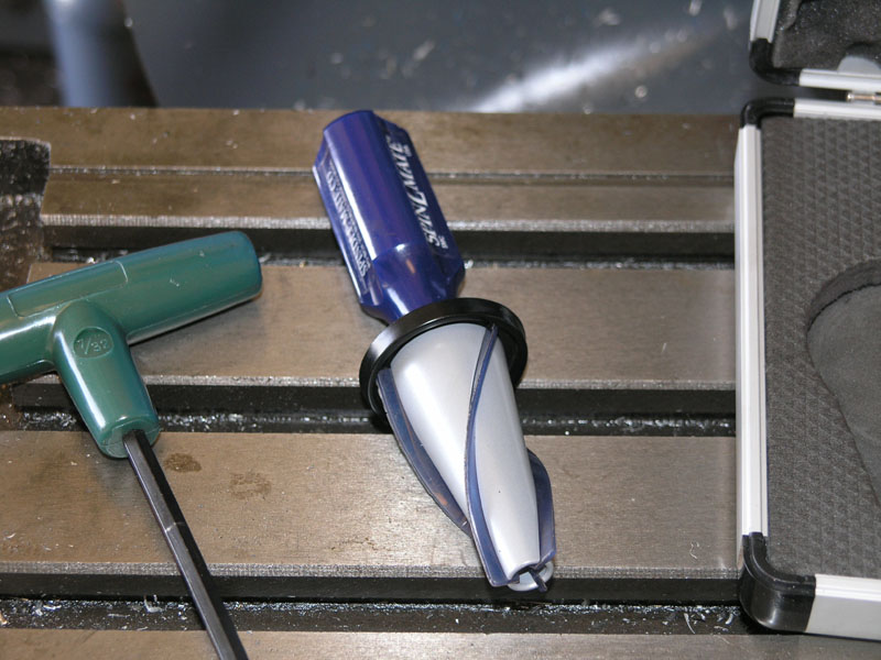
It's just a handy way to clean up your spindle taper and make sure there are no chips stuck up there.
Second, the "Traminator" and my collection of tramming accessories:
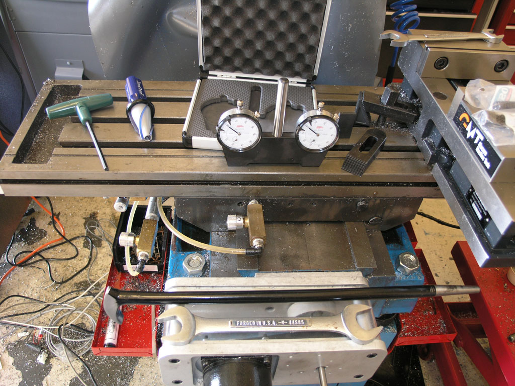
The Traminator and Case in Back, Pry Bar and Wrench in front...
The Traminator (my name for it), was a gift from my brother for Christmas. This one is made by SPI and its very nicely built. To calibrate, set it on a flat surface and zero the two dials. Insert in your spindle, bring it down in Z until the dials read, and adjust tram until they both read the same value. Super easy and fast! I had been tramming with an Indicol and DTI, but I like this a lot better. It's just faster and easier for me. In this case, I could tell from some face milling I'd been doing I was out of tram in both X and Y. The Traminator made short work of it. I use the pry bar through a hole in the side of the spindle to get a little more leverage, and tap on it with a mallet to tram. It's real important on the IH mill to carefully watch what happens to tram as you tighten the locking bolts too, and that is particularly easy with the Traminator.
First Chips from Rockwell Delta Bandsaw
Finally got a chance to hook up a VFD to my new/old bandsaw so I could see it run. It's set up for 3 phase and the VFD I had laying around for eventual use with my mill was the easy way to fire it up. I made a few chips. Blade needs adjusting, and it also has the wrong blade in it for metal. This 20" bandsaw (Rockwell/Delta 28-365) seems to have been babied in a woodworking shop for years. I have a hunch when I get it all tuned up it will cut through metal like butter, especially aluminum. It's already very strong.
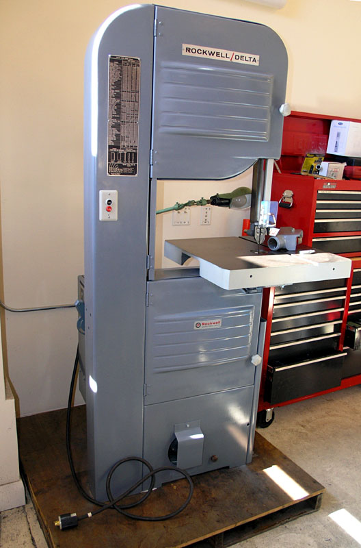
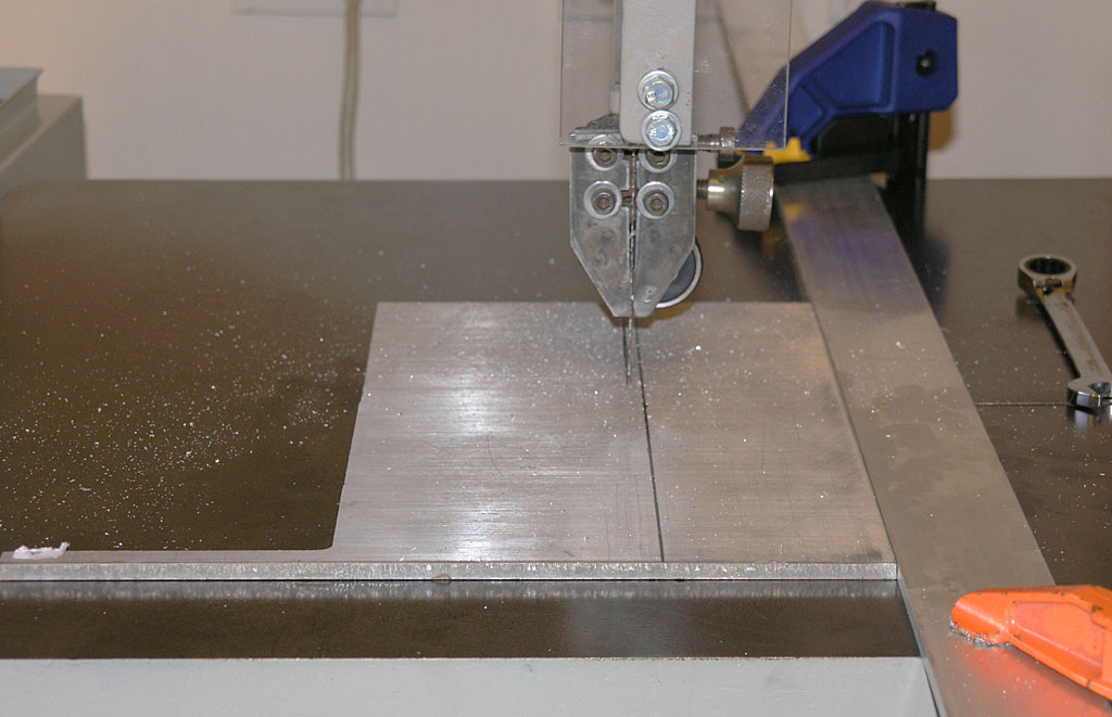
First chips...
I'll need to get busy making some accessories for it too. No form of fence or miter guide came with it, for example.
2/13/10
Brian Rupnow Shows How to Turn Tapers With a Boring Head in Your Tailstock
A picture from this HSM thread is worth a thousand words:
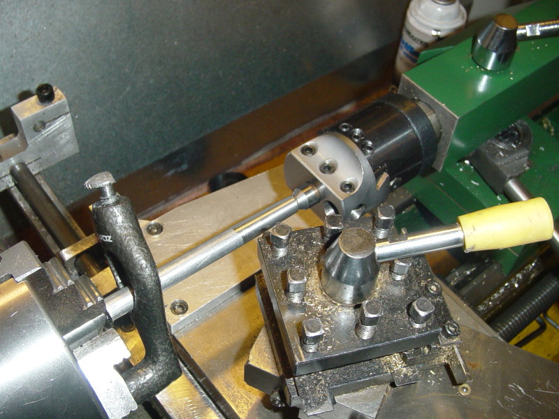
It's a "dead" center, so you'll have to work accordingly!
2/9/10
Homann ModIO Pendant Kit for the IH CNC Mill
I started building my Homann ModIO Pendant Kit for my IH Mill this evening. Very nice kit, I think I will like it a lot! You can follow my build progress on my pendant page. Here are a couple of pix of progress so far:
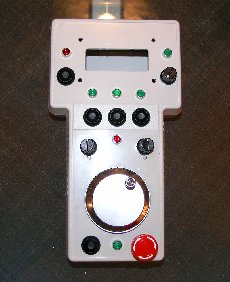
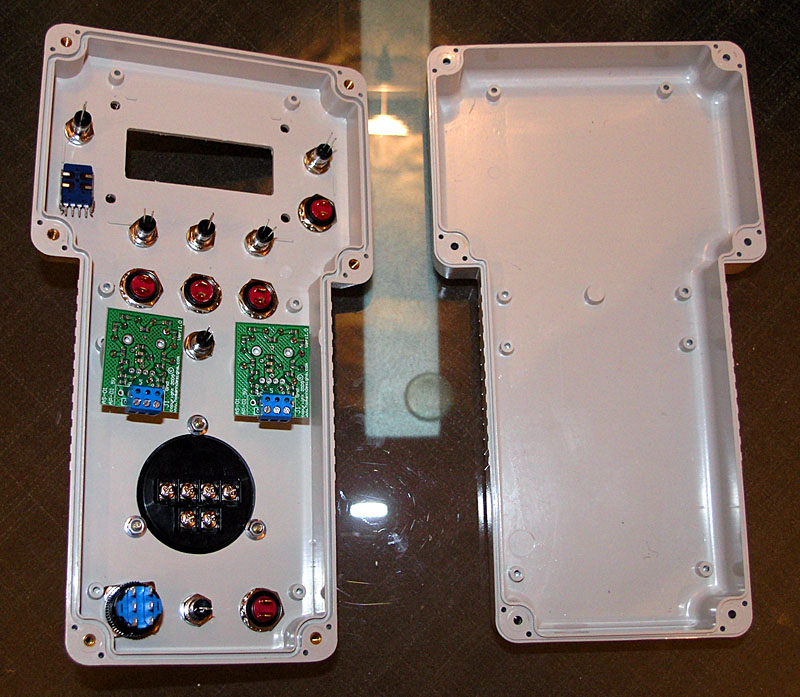
I'm planning a leisurely pace with this kit, so I'm not in a rush to stuff it together. I want it to come out nice and work well.
2/8/10
Neat Bandsaw Tricks
Cleaned out some of my notes and consolidated them onto my mini-bandsaw page. There's some good tricks in there to get more from your mini-bandsaw. Every time I think mine is done because I got some better saw, I wind up making a little mod to it and bringing it back into service. The last rumor of its demise was due to my DeWalt Multicutter carbide chop saw. I will admit, it took me a couple years to bring it back, but I finally did. I mounted it on a nice cart so it was more stable and at a better work height, and I added a little table to it. I used it mostly in vertical mode at that stage. Handy to pop it on to cut little pieces quickly. A lot less drama than the chop saw too.
The latest rumor of its demise is due to the hulking big 20" (thought it was an 18", but got to doing some research and checking the nameplates and it is a model 28-365 Delta/rockwell 20" Bandsaw, woohoo!) bandsaw I got. It is not yet operational. Spent some time tinkering this weekend to get it going. Motor just hums, so I'll have to suss that out. My brother will likely be invaluable as he helped me get my big compressor with a similar issue going.
We'll see whether I can come up with a good use for the little guy, but meanwhile, the updated page should help others with a saw like this.
At the moment, the other tool I almost never use and need to upgrade to make it more useful or get rid of is my drill press. Of course I have a drill press page full of potential upgades too!
2/6/10
Try a Corncob Rougher to Stop Chatter
Corncob roughers are great. They're those endmills that have the serrated edges. They cut through most materials much more freely than conventional endmills, but my friend Pete says they are da bomb when dealing with chatter, and particularly if you're fighting a small machine's rigidity limitations.
I'll have to try one out the next time I'm having a problem.
2/4/10
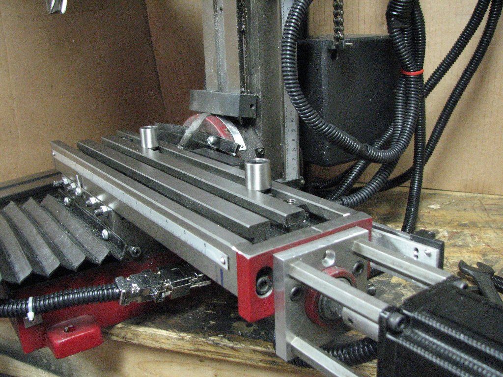
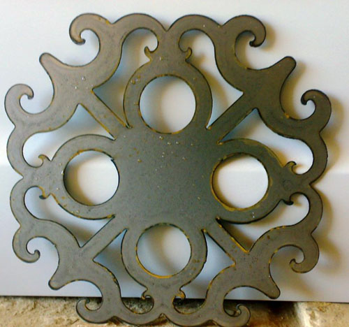
Armadillo Way Covers
Or at least that's what someone called this style and I liked it:
Cutting Steel on a Sieg X2
I recently had a G-Wizard user contact me about cutting steel on his Sieg X2. He was not happy with the results he was getting and couldn't go near as fast as G-Wizard was telling him to. I wanted to pen some thoughts for this fellow and others who are in the same boat. Sorry for the long post, but it touches on some of the seminal issues that have to be understood right from the start of your machining learning curve.
First, the difference between working steel and aluminum is almost like night and day. Hoss remarked recently on CNCZone that he bought an RF-45 mill so he could work steel and that he had only really been happy working Aluminum on his Sieg X2. I can tell you that even with the RF-45, steel is more challenging to get good results with.
This fellow was trying to square some ¼" angle iron to make some vise clamps. As he put it:
The angle iron was very wavy and needed some squaring. But when cutting, the mill sounded like I was shaking it to pieces if I tried side milling at .030 DOC and around 800 RPM using a 1/2" HSS endmill. The faster I fed the more it shook.
What's up with that?
I remember manual milling steel on my RF-45, a much stouter mill, before I CNC'd it and got G-Wizard. At the time, it would've been rare for me to take more than about 40 thousandths depth of cut turning the handwheels in steel. It just seemed too gnarly and I was in no great hurry. Trying to cut 30 thou on a much lighter mill might be the issue right there. I've since gotten a lot bolder with the CNC, but let's look this situation over carefully.
First up, there are actually three issues to be concerned with. One is what the recommended feeds and speeds might be and how to go about administering those manually. Two is what the machine can actually handle. Three is the possibility of chatter. Let's consider each one in turn.
What are the Recommended Feeds and Speeds?
For a side milling cut of ¼" angle iron at 0.030 depth of cut with a ½" 4 flute HSS Endmill, G-Wizard gives back 1015 rpm @ 37.278 IPM. For a gearbox machine, you'll have to take the nearest spindle rpm and override G-Wizard with that value. In this case, he says 800 rpm, which drops the feed to 29.394 IPM. Keep in mind that recommendations are just the starting point. It's up to the skills of the machinist to take it forward from there.
Next problem is how to manually feed at such a rate? I always converted to handscrew turns/second or seconds/handscrew turn (if it was a slow feed) and then just counted them off-it'll be close enough. In this case, the handscrews are likely 100 thousandths per turn, 10 turns an inch, so we need 290 turns a minute. That's about 5 turns a second, pretty quick!. Faster than a manual machinist will likely be comfortable feeding.
But in this case, the mill is shaking like crazy with a feed that is probably much slower. Let's say 1/5 of that (1 turn a second). So he was going maybe 5 or 6 IPM at best and no way would the mill go faster without shaking apart. Time to consider:
What Can the Mill Actually Handle?
This brings us to issue number two: can this mill actually handle the recommended feeds and speeds? Note that this is a fairly complex question. A less than completely rigid setup, a small mill, and a cheap cutter can combine to make it really hard to hit recommended feeds and speeds.
Let's analyze the symptoms of two problem areas:
- Cutter is getting burned and dulled very rapidly. Lots of heat in the cut. The cutter may be discolored. This is a sign of too much SFM. Need to cut back spindle rpms. Many hobby mills have such low maximum spindle rpm we don't see this one too much. Look at the chip color on steel. Blue will kill HSS cutters. Straw is about right, and silver will give you longest life. Carbide is capable of amazingly faster spindle rpms.
- You are breaking endmills. This can be the sign of too much chipload. Need to feed more slowly. OTOH, this can also be a sign of inadequate chip clearance too. If chips are packing into the cut the endmill's job is tremendously more difficult. Make sure they're being rapidly cleared.
This individual reports the cutter is raising a burr and acting dull as well as there being a ton of vibration. The cutter may have started out pretty dull or low quality, so that is something to keep in mind. The vibration may be chatter, which is a harmonic vibration affected by speeds and feeds, but not a feeds and speeds problem per se. I lean to the theory that this is chatter, BTW. Chatter is a bad combination of rigidity and resonances in the machine.
Let's put the chatter theory aside for later and look at whether the mill can handle the cut.
In this case, G-Wizard assumes a chipload of 0.0022. We may want to take that down some if dealing with cutters that are well used and/or not name brand. A low end value might be as low as say 6 or 7 tenths of chipload. FWIW, that's actually 6.5 IPM on the handle. Too little chipload, BTW, can lead to as much trouble as too much, so don't arbitrarily assume you want to always crank it down. If you want to always reduce it, you can always enter a chipload adjustment in G-Wizard's machine profile. For a Sieg X2, I would be tempted to enter at least some reduction in chipload from the recommended values.
In terms of how difficult that cut is, I like to use HP as a measure. G-Wizard tells us this cut is 0.15 HP if you follow recommended feeds and speeds. So 0.15HP is being fed into the workpiece, your setup, and the mill, and it must resist that force successfully to do the job. FWIW, the same feedrate in 6061 aluminum requires about 1/3 as much HP. That's a decent rule of thumb-the same cuts in steel are 3x more demanding than aluminum. Put another way, whatever your mill could do in aluminum, you can do 1/3 that much in steel, and we're talking the mildest steel, not tool steel or stainless!
Let's turn it around. Is the desired cut, 1/4" deep, 0.030" wide, the sort of cut one would make in aluminum on this machine? I suspect it is. But if steel is 3x more difficult, would the machine be happy cutting say 0.090" wide? Probably a lot less happy.
On my IH mill, I set a 1 HP limit on G-Wizard that I've learned from experience is a good number. That's half the rated 2 HP of the motor because I know if I start to get north of 1 HP I am working my mill pretty hard. I can do it, but I need to take extra care with every aspect of the setup. That's not to say the mill is incapable of doing more, just that I, as the machinist, will have to work harder to ensure success above that level.
I don't know the limits of the Sieg, but I wouldn't be surprised if 0.15HP are very close to equivalent to 1HP on my mill. So, we have both a chatter-prone situation as I will discuss shortly, and we are at the edge of prudence.
What about Chatter?
Okay, let's now go back and focus on chatter. Since it is a resonant effect, you can change feeds and speeds to get away from it or you can increase the rigidity of your machine, tooling, or setup to help resist the vibration.
I said before I suspect chatter, but why? First, one of the big symptoms is lots of vibration and often a sharp sound (hence the name "chatter"). Second, The X2's have a notoriously weak column, which will be prone to chatter. Think attaching your spindle to a tuning fork. Making one of the column mods to stiffen it would really help a lot. Also, the writer mentions that the part was in the vise and "sticking out like a diving board." That's a sure recipe for chatter and low rigidity. Thin plates love to vibrate like tuning forks, which makes me lean even harder to the theory this problem is chatter.
What to do about the chatter? If you want to vary feed or speed, try faster first according to a lot of the sources I have read (Kennametal, for example). In fact, you can systematically map the resonance character of your machine with each cutter, but that's a topic for another post.
Changing feeds and speeds is quick and easy, but it won't always work. The next step would be to find ways to hold the angle iron much more securely and with as little sticking out as possible. I recently built a very stout set of vise jaws (my Vise Jaws of "Doom") to get away from some chatter problems in surface finish. This was while trying to engrave ¼" 6061 aluminimum in a 6" vise. I had maybe 2" sticking out on either side of the vise and no chatter was audible, but you sure could see it in the cut with even the lightest face milling passes.
Here are some ideas for how to systematically deal with chatter:
1) Vary speed and/or feed to get outside the resonance zone. Try increasing feed, then decreasing, then try increasing followed by decreasing speed.
2) Change axial or radial depth of cut. There is a large body of literature on chatter that suggests the resonant frequency of chatter varies with axial and radial depth of cut for a given machine and tool, but regardless of material or workpiece. Changing the axial or radial depth of cut may move you out of the zone of resonance.
3) Make the setup more rigid. Leave as little of the workpiece as possible unsupported. Add more clamps. Etc.
4) Make the tooling more rigid. Use a larger diameter endmill. Reduce the length and "stick out" of the cutter.
5) Make the mill more rigid: Lock every axis but the one that has to move. Tighten the gibs as tight as you can while still being able to move the handwheels smoothly. Make sure the ways are well lubed so you can run your gibs even tighter. I even went to the trouble of doing an epoxy/granite fill on my machine's base and part of the column. I estimate an increase of 15-20% in the rigidity as a result. I have already mentioned making the column to base connection stouter and there are many other's postings on places like CNCZone to help with ideas there.
6) Prep the workpiece. The writer mentions the surface of the angle iron was "wavy". Being a resonant phenomenon, chatter can feed off those waves. In fact, a flat surface that has gotten wavy because of a chattery pass is even more chatter prone afterward. Try to break up the waves if you can. I'd be tempted to hit it with my big disc sander if all else failed.
Last thought: this particular poster asks about G-Wizard's climb milling recommendations. As the G-Wizard docs (and many other sources) will say, if your machine has backlash, you'll need to be very very careful climb milling, and unless you have a lot of experience, you should just avoid it altogether. On a real light machine like a Sieg X2, I just wouldn't try it unless I had ballscrews to reduce backlash to a minimum. On my IH, before I had ballscrews, I used to get away with it by taking very light cuts with relatively small tools. A ¼" endmill taking 15 or 20 thousands was the maximum I would attempt. In addition, I used to really tighten up the gibs and lock and unused axes. The handwheels were very hard to turn, and the machine is relatively heavy, so it was tough for the cutter to drag the table into the backlash.
2/1/10
Hoss Uses Slot Pins for Big Jobs
What to do when the job is bigger than your mill's capacity? Hoss uses slot pins as an alignment guide:
Once the pins are trammed in properly, and you can design them so the tramming is automatic based on their fit to your table slots, you can be assured that any work you clamp up against them is properly aligned with the table.
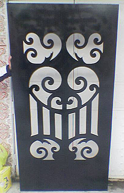
Cool Plasma Table Work from Algeria
DZStar posted a video of his shopmade plasma table and some of the designs he has made with it on CNCZone:
This machine uses a simple spring-loaded Z-axis (no electronic torch height controller) to maintain the torch distance from the workpiece. The torch is an inexpensive ($700) Italian unit. All in all, it shows just how easy and simple it is to create a plasma table that can do some pretty amazing work. Here are some of his designs:
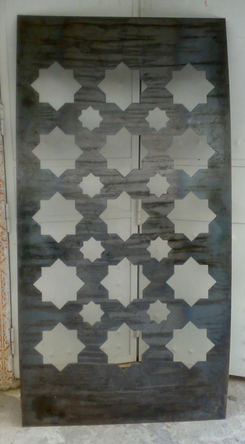

Doors with intricate mosaic patterns...
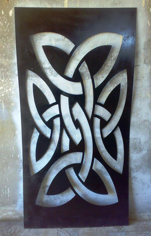
My personal favorite!
1/4/10
Micro-Miniature Tormach Tooling System
A lot of folks are adding auxilliary high speed spindles to their mills for things engraving and running very small endmills or twist drills. G-Wizard's recommended rpm for a 1/16" HSS twist drill is over 12,000 rpm, for example. Smaller drills, like you would run to drill a PC Board, require even more speed. In fact, there is a whole market out there for companies that sell small very high speed "sensitive" drill presses for this sort of thing. But, they're not CNC.
It's pretty easy to attach such a spindle to your CNC mill's head, and people have done this with everything from Dremel's, to their higher quality Proxxon cousins, to routers, laminate routers, and all sorts of other appliances. Take a look at the page I linked to for some ideas. This is a pretty handy thing, but pretty soon, you're wishing for some of the comforts of home. Perhaps a toolchanger is out of the question, but at the very least, a way to make the cutters repeatable in Z so you don't have to do a touch off for the tool table every time would be nice.
Enter this great idea I saw on CNCZone:
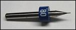
0.020" Endmill with a Distance Ring...
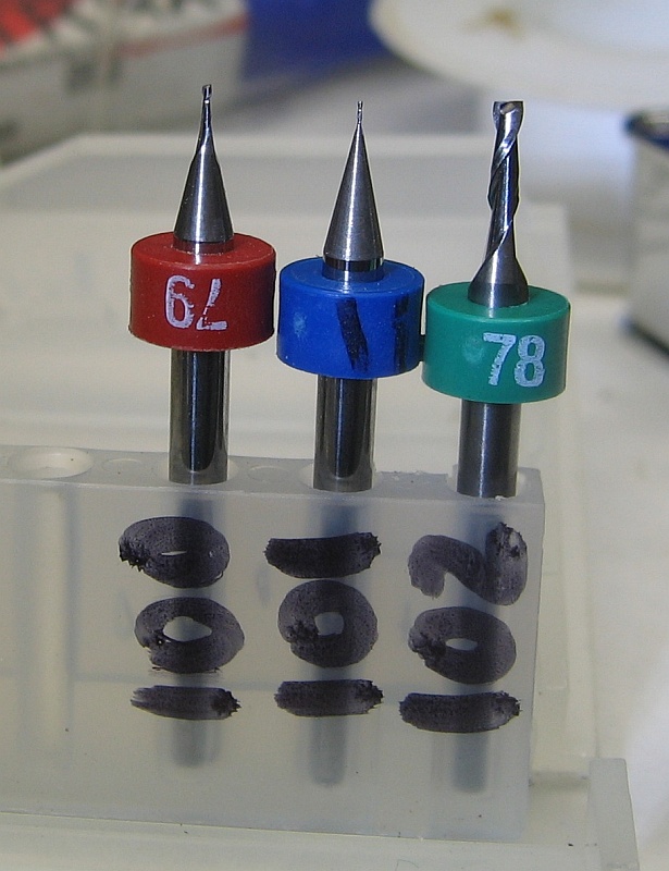
First attempt at a holder with Tool Table numbers. Those cutters are so tiny!

Here is a little fixture to help us press the ring onto the cutter...

Of course when you have a CNC at hand, a nicer holder is only a matter of time...
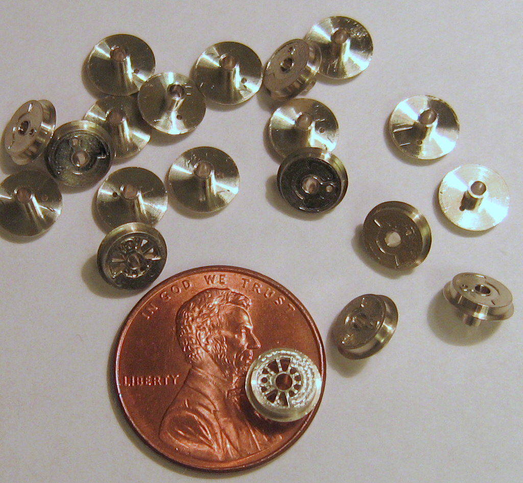
Tiny train wheels next to a penny...
All this micro-machining work was done on a Tormach with an auxilliary Proxxon spindle. I have to say I am very impressed. The requirements for runout and precision have to go way up at these scales. The distance rings are available from PC Board drilling suppliers such as LPKF.
Very cool!
1/3/10
A Drillpress Table Lift
Jerry over on HSM had this nice table lift for his drill press to show:
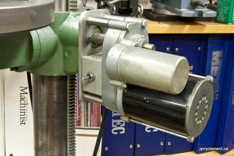
Nice use of a surplus reduction-geared motor, and very compact. I think I'd have mounted the switch up on the drill press head, but that's just me. I have a whole page of drill press mods that I will be adding this one to!
Hoss Machine Has a Nice Rack
The piccy says it all:
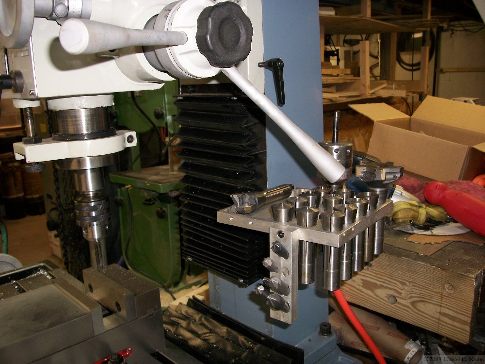

It pivots out of the way...
Scraping Video
Scraping is the preferred method when surfaces need to be flat to a high degree of precision, such as when making machine tool ways. lt's a painstaking manual process that I've often wondered about. Here is an excellent video of a Kitamura machinist scraping a casting for one of their machine tools:
Lots of good learning here about the angle to hold the scraper and you can see how he aims for the bluing (which in this case is black). It also looks to me like his scraper is set up so he can apply force with his hip.
Shopmade Motor Couplers
Couplers to link your stepper or servo motor to the leadscrew or other drive mechanisms can be surprisingly expensive. It's not hard at all to make them in your shop. Here's some Oldham-style couplers made as part of a Weiss mill conversion described on CNCZone:

The plastic inside parts where bought as replacement parts very cheaply, which meant only the metal ends had to be machined. As you can see, they're very simple!
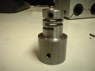
Another example, done with a slitting saw...
What's nice about making your own couplers is you can accomodate whatever special requirements you may have. I've had to bore store-bought couplers to fit a shaft, for example.
|
Do you want to be a better CNC'er in 37 Seconds? Get Better Tool Life, Surface Finish, and Material Removal Rates Fast. It's that easy. You can install and get results now.

|
||||||||||||||||||
| ||||||||||||||||||