|
|
|
|
|
|
|
Want to be a better CNC'er? Get our weekly newsletter plus a package of greatest hits, special tips, and more, all for free. I'm Ready to Be a Better CNC'er, Hook Me Up! |
ModIO MP-03 Pendant for IH CNC Mill
I've been wishing for a pendant lately. Grabbing the laptop and dragging it up close so my tired eyes can see to align things is okay, but a pendant sure would be nice! So, I asked my wife to order a Homann Designs ModIO Pendant kit for my birthday. I love to build electronic things, and this gadget sure enough has more bells and whistles than any pendant I've seen available anywhere else! I need another project like a hole in the head, but what the heck. This is something nice and quiet I can do in the living room (bet the wife didn't think of that!) in the evenings.
I first learned about this pendant from a thread on CNCZone. The piccies looked super cool and Scott Poppa Bear Shafer wrote a nice Mach3 plug-in to support it. Having done business with Peter Homann before and (he runs a great firm), I figured how could I go wrong?
What follows is the story of building it...
Unpacking the Kit and Getting Started
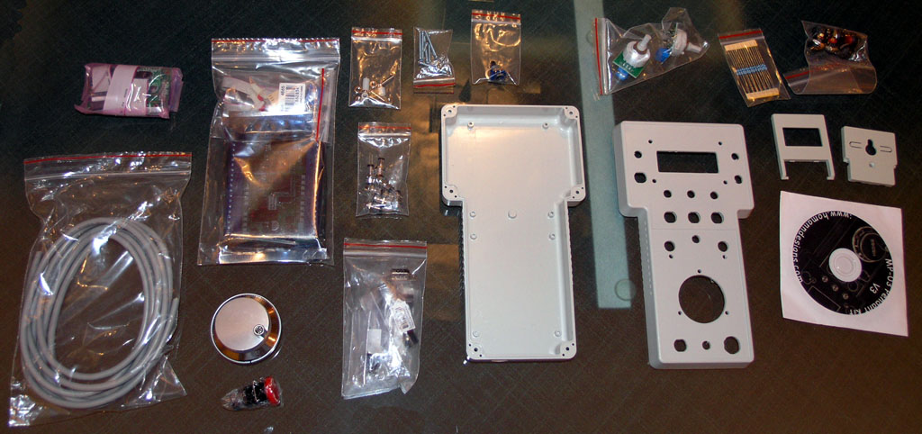
The parts kit is very complete!
The parts kit for the pendant is very complete, and the parts are very high quality. I really like the rubber membrane covered pushbuttons and the led indicators in their little bezels. The plastic case is also nicely machined. Lay out all of your parts and make sure everything is there before proceeding!
Also, make sure you have the most recent schematic for the project. A revision (v4) came out as I was building mine, and I got it from this CNCZone thread.
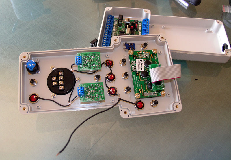
Part 1: Mount the Components on the Case
After checking over your parts to make sure everything is there, the next step is to mount everything to the case. This is a straightforward and fun operation. Just use a needle-nosed pliers to tighten the locknuts for each component. Refer to the pictures below for their locations:
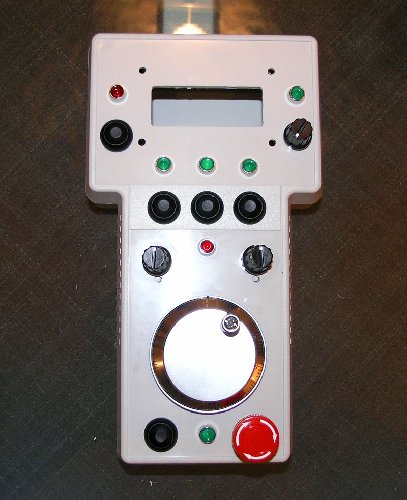
I have the optional fancy E-Stop button. The main thing is to get the red LEDs in the right locations. The rest of the parts only fit where they belong.
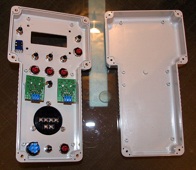
Don't over torque the locknuts--this is just plastic!
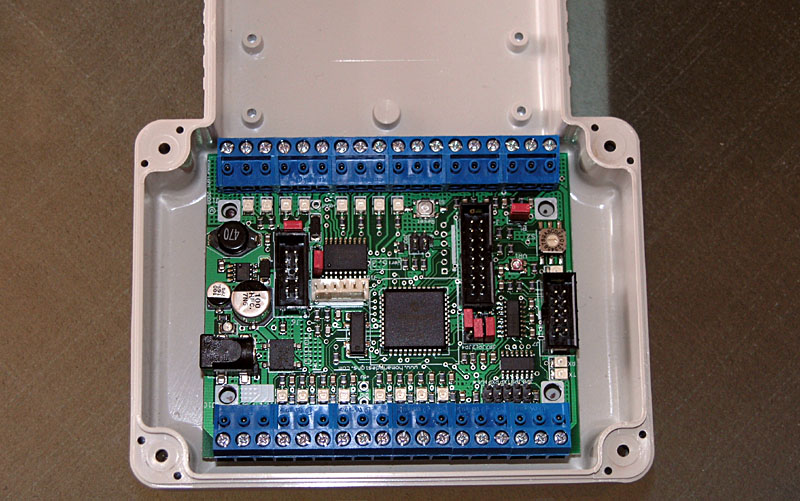
Next, we need to use the ModIO as a template to mark out where to drill the mounting holes for it:
Mark the holes with a Sharpie or similar...
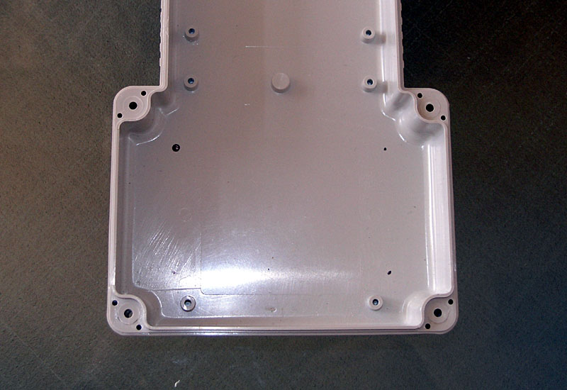
Marked so you can drill...
<To be continued>
Part 2 Making the Ground and +5V Wiring Harnesses
I want to keep the wiring for the pendant as neat as possible, so I'll be making up some wiring harnesses to try to keep things clean. Refer to your wiring diagram on the included CD to see what's needed.
The harnesses are primarily about distributing Ground and +5V to a bunch of places. You can obtain the Ground and +5V from the ModIO board, which has several pins for the purpose.
Ground needs to be distributed as follows:
Ground Wiring Harness:
Source: ModIO J1 Pin 4
Destinations:
So, we need a harness of the appropriate length to deliver Ground to 8 locations.
+5V Wiring Harness
Source: ModIO J1 Pin 1
Destinations:
Note: I have specifically excluded the +5V and Ground connections for the MPG (manual pulse generator) as I will wire these directly. Why? It's a special device and I've decided to pamper it with special treatment.
I use simple "hook" splices when making the harness:
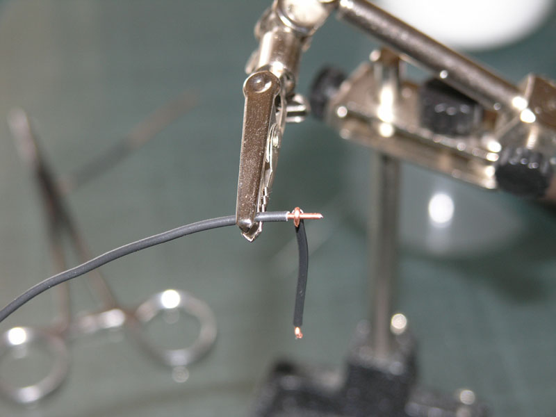
A simply "hook" splice ready to be soldered. There's room on the right to attach another "hook"...
Keep the exposed wire to a minimum and make all the bends with your needle-nosed pliers. If you need to expose wire in the middle, rather than at the ends, strip more from the ends so that when the insulation is slid it won't cover the end.
Work slowly and measure out each length of wire carefully so there is enough you're not stretching and bending things, but not so much it makes a mess. I just went point to point, soldering each segment as it was measured and completed. I wound up with three of the "hook" splices. I could've slid some heat shrink tubing over them, but the wire is solid so it isn't going to move around and short anything. Plus, this one is ground. I'll take a little more care with the +5V wiring. I like to use black wire for ground, red wire for power (+5V) and green wire for "signal".
The ground wiring harness. That's all the pushbuttons on one terminal, plus two of the rotary switches. I still need to pick up ground on the remaining rotary switch which is just above the LCD display. I'll just "hook" onto the topmost pushbutton switch that is near it.
|
Do you want to be a better CNC'er? Get Better Tool Life, Surface Finish, and Material Removal Rates.
|
||||||||||||||||||
| ||||||||||||||||||