Chip Thinning, Lead Angles, and Ballnose
Compensation
Getting the right feeds and
speeds is essential to producing good results efficiently with machine
tools, but it's not particularly easy to optimize feeds and speeds. There
are basic formulas and rules of thumb that the majority of machinist's
go by. For any material and cutter combination, you can look up the recommended
Surface Speed (SFM, or Surface Feet per Minute and SMM or Surface Meters
per Minute) and Chipload (inches of cut per tooth of the cutter). Various
simple formulas then yield a recommended spindle rpm so as not to exceed
the recommended SFM and a recommended feedrate to deliver the chipload
to the cutter teeth. Easy, right?
Not so fast!
Would you believe that especially for light cuts, the basic math combined with SFM and chipload tables often gives results that are wrong and radically increase the wear on your tools?
The reason is that there is more going on here
than meets the eye. For example, if I poke around various endmill manufacturer's
literature in search of speeds and feeds for steel, I can get to a page
like this
one from Niagara cutter. First thing to note is that the recommended
chiploads and SFM vary depending on the exact operation being performed,
and in particular, the depths of cuts. If you're just using the basic
shop math around SFM and chipload, no such compensation is available.
I have built compensation like this into my G-Wizard
Machinist's Calculator, but trust me, it isn't so easy just to do
it by hand. You'll be constantly referring to pages like this.
OK, so let's say we're going
to do some peripheral (edge) milling to profile a part made out of mild
steel using a 1/2" uncoated HSS 4 flute endmill. We plan to take
fairly shallow finishing quality cuts of 5% of the cutter diameter. Further,
let's do a pretty deep cut axially, a full cutter diameter of 1/2".
So if I am profiling a 1" high part, I can make a full pass by going
around twice and cutting 1/2" each time.
What feeds and speeds should
we use?
The Niagara page says for cuts
less than 1/16 of a diameter (5% is 1/20), we want 210 SFM and a chipload
of 0.0035. If I plug all that into G-Wizard, but ignore the chip thinning,
I get the following results:
Radial Depth Ratio of 5% =
0.015" depth of cut
210 SFM and 0.0035 chipload
gives us 22.46 IPM feedrate and a 1600 rpm spindle speed.
Is that the right speeds and
feeds?
Yes and no. It's certainly
what the majority of folks would use. In fact, they might even be less
aggressive than that.
Let's see what G-Wizard would
suggest by default and why:
For the same depth of cut and
cutter, G-Wizard wants a little slower SFM of 160, and a little less aggressive
chipload at 0.003.
The spindle speed works out
to be 1200 rpm due to the lower SFM, but the feedrate is now 84.69 IPM!
How can we go so fast?!??
The answer lies in chip thinning.
Because we're taking such a shallow cut, you have to speed up the feedrate
just to get to the same chipload as on a much heavier cut. In fact, any
time you cut less than half the tool's diameter radially (i.e. when viewed
looking straight down the spindle axis), your chips will be thinner than
expected.
It's easy to understand the
geometry that leads to chip thinning:
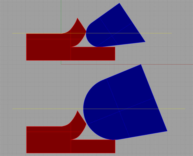
The blue chip
is a shallower cut. Note how thin it is at its widest compared to the
red chip from a deeper cut...
The blue chip
represents a very shallow cut, and the red chip a deeper cut. Note how
thin the blue chip is at its widest compared to the red chip from a deeper
cut. You can see that the chip gets thicker all the way up to the point
where we've buried the cutter to 1/2 its diameter. That's the thickest
point.
Chip thinning
simply answers the question, "How much faster do we have to go so
the maximum width of the blue chip is the recommended chipload?"
The differences
in required feedrate can be quite substantial. In this case, we needed
to be going almost 85 IPM instead of 22.5 IPM, over 3x as fast. And remember,
this isn't some hot rod feedrate that is guaranteed to wear out your cutters
before the even finish the first pass. This is the speed you need to reach
to get the chipload you thought you had already chosen.
You can see where
this kind of circular geometry affects a lot of different cutter combinations.
We talked about peripheral (edge) milling first. But it's a function of
surfacing too, which is mostly about edge cutting down at the tip of the
mill. There is no impact on plunge cutting where we move straight down.
Surfacing with a big face mill or a fly cutter is impacted, however.
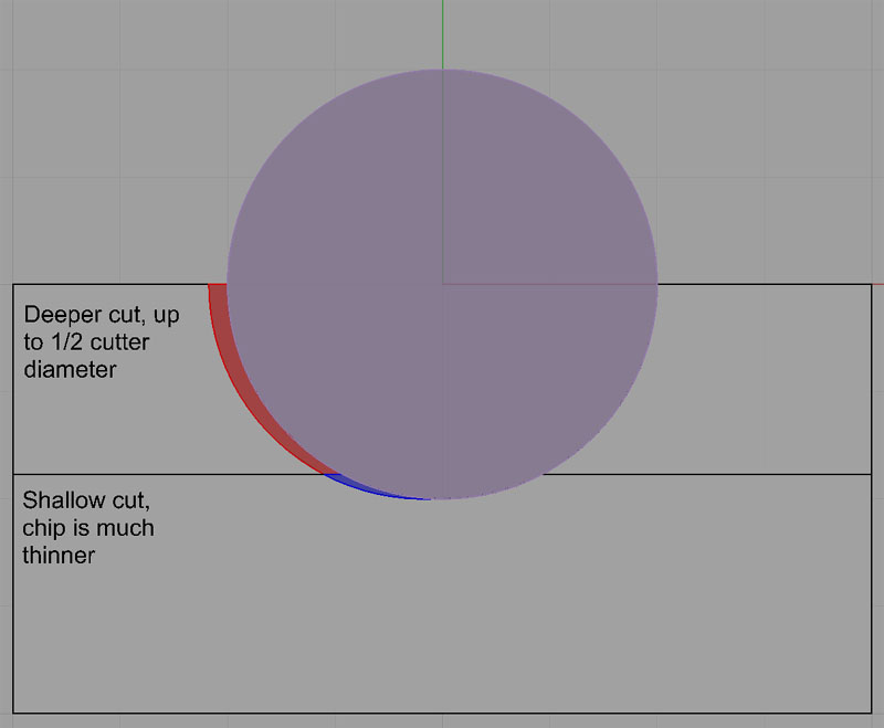
How about button
cutters, or as they are sometimes called toroidal cutters? These are indexable
face mills and endmills that use round inserts. The diagram above shows
the same effect, its just that instead of the spindle axis coming right
out of the screen, it goes straight up. So we want to run chip thinning
calculations for them too. Running one without chip thinning may account
for why so many people find them to be gentle cutters--they're taking
a lot less cut than they expect.
How about lead
angles? Some facemills cut a 90 degree shoulder, others may cut a 45 degree
or other angle. Similar geometric effects apply, and there is compensation
needed for lead angle that G-Wizard also builds in.
Ballnosed cutters
are another problem child when you try to use the most basic speed and
feed calculations. In this case, it isn't just the feedrates that have
to be considered, it's also the spindle rpm. If we are running a 1/2"
ballnosed endmill, and we are profiling, with a depth of cut of 0.040",
the cutter is only 0.040" down into the cut. The effective diameter
of the cutter is no longer 1/2". The diameter of the ball at the
top of the cut is actually 0.2713", so we need to spin the cutter
faster--about 1800 rpm instead of the 1200 rpm we had been using with
a regular cylindrical endmill.
These are all
forms of compensation that affect the feeds and speeds of your cutters
quite a lot. I've built all of them into G-Wizard so I can quit worrying
about it. The math to do it is available on the web if you Google for
it, or you can just use a calculator like G-Wizard to figure it out for
you. There are several of them out there. Some CAM programs do this kind
of compensation as well.
Here's a video from my "CNC Chef" column over on CTEMag that goes over Chip Thinning:
How Much Feed is Too Little Feed?
Now here is the dark side of
chip thinning and similar compensation: it isn't just about going faster,
it's about tool life. Amazingly, just when you think you're really babying your cutters by reducing the feedrate and taking light cuts, you're actually giving them the worst possible treatment. Surface finish may improve (because the tool is essentially burnishing the workpiece), but tool life will go way down. Consider a magnified view of your cutting edge versus the material:
Cutter edge radius centerline travels along the yellow lines. If the radius is too large relative to the depth of cut (bottom), all the force goes to pushing the chip under the edge. This is the "rubbing" effect you'll hear talked about when feedrate and hence chipload are too low. Our Feeds and Speeds Calculator, G-Wizard, will give you a warning whenever rubbing is a problem, and those warnings can rally save your bacon.
Tool manufacturers will tell
you that too little feed is just as bad for tool life as too much feed
(or too much spindle rpm). But how little is too little? That part is
seemingly hard to find out. I went fishing around with Google to try to
find what speeds and feeds result in a "burnishing" effect with
tools. Here is what I found:
- Article
on hard milling: 0.0008" per tooth is definitely burnishing because
it is "less than the edge hone typically applied to the insert."
- De-Classified
1961 Batelle Institute report on aerospacing machining of super-alloys
says an IPR greater than 0.0035 will result in burnishing and likely work
hardening of these alloys. Interesting how well this number agrees with
the one above for a 4 flute cutter. 8 tenths times four would be 32 tenths.
- Kennametal
says the "highest possible feed per tooth will usually provide
longer tool life. However, excessive feeds may overload the tool and cause
the cutting edges to chip or break." So feed as fast as you can until
you start to chip or break edges. They reiterate this under work hardening.
One wonders whether rubbing leading to work hardening isn't the principal
risk of cutting with too-low chiploads with respect to tool life in susceptible
materials.
- Another
reference, like the first, to keeping chiploads higher than tool edge
radius. In this case, IPT should be greater than 0.001". This is
once again an article on hard machining where work hardening may be a
factor.
- Minimum
chip thickness is 5-20% of the cutting edge radius. Below that level,
chips will not form and the cutter will "plow" across the workpiece
causing plastic deformation and considerable heat.
- Ingersoll
says that as a general rule carbide chiploads should not be less than
0.004" or you run the risk of rubbing which reduces tool life and
causes chatter.
I take away two things:
1. If you cut too little, you
run the risk of work hardening if your material is susceptible to it.
That will wreck your tool life if you are over-stimulating work hardening.
2. If chip thinning and other
effects leave you cutting much less than the cutting edge radius, you're
rubbing and not making clean chips. That will heat the tool and material
and drastically reduce tool life.
Figuring out the work hardening
part is easy. If your material is susceptible, keep the chipload up. Figuring
out the whole cutting radius issue is harder. Most of the time we don't
know what the cutting radius is. I'm not talking about tip radius on a
lathe tool, for example. I'm talking about the actual radius of the sharp
edge. In other words, the smaller the radius, the sharper the tool. A
lot of carbide inserts are pretty blunt. A chipload of less than 0.001"
may very well be too little. Modern tools for aluminum are often much
sharper, and can take less chipload. In general, indexable tools are usually
less sharp than endmills, so they need higher chiploads.
It's ironic that just when
you think you are taking it easy on a cutter with a very light cut, you
may be doing the most damage of all due to rubbing.
Why chance it though? Use a
calculator like G-Wizard to figure out how to deliver the manufacturer's
recommended chipload by increasing the feedrates. Not only will the job
go faster but your tooling will last longer.