|
|
|
|
|
|
|
Do you want to be a better CNC'er in 37 Seconds? Get Better Tool Life, Surface Finish, and Material Removal Rates Fast. It's that easy. You can install and get results now. |
April Through July 2008 CNC Cookbook Blog Archive
7/20/08
Finished Epoxy Granite Filling Around the Column Bolt Pipe on My IH Mill
Just to make sure I was revved up to go to work on the mill this morning I watched a bunch of CNC videos on CNCZone. Then I went down, donned my nitrile gloves, and got back to making my epoxy granite mud pies:
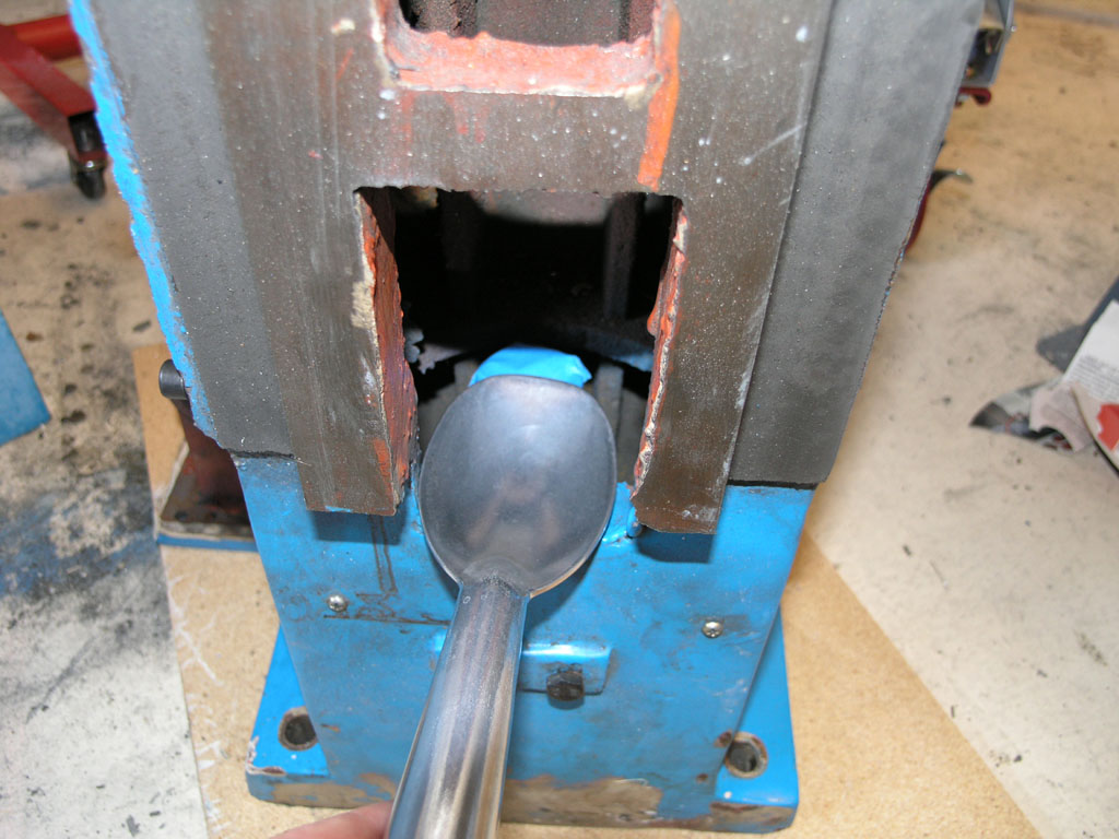
Filling the cavity through the narrow slot was easiest with a cheap ice cream scoop I bought at the hardware store for $4...
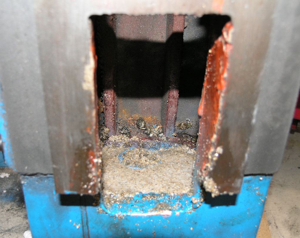
I filled up to about 1/2" from the top of the pipe, and then I switched to a pure sand mixture to make sure the top was free of rock edges sticking up...
7/15/08
Started Some Pages for Bobs No.1 Steam Engine
This will be a very long term project but I started some pages to keep track of it on. Biggest news here is I've changed the steam port design based on a clever suggestion someone made to me.
I cut a pocket with a 1/8" endmill so I don't have to angle the ports and use a funny shaped piston...
7/13/08
Still More Epoxy Granite Pouring, But No Pix
I filled most of the base up to about 1/2" below the top of the pipe for the central column bolt. I want to let that set up and then carefully take the mixture the last little bit to the top of pipe. The reason is that its real tight confines inside the column and I wanted to do the last little bit with a mixture that's wetter and more sand with less gravel.
Some Steam Engine 3D Modeling
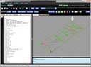
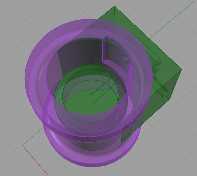
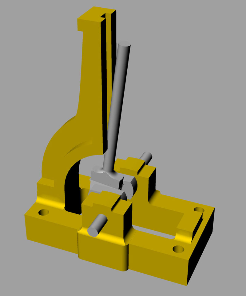
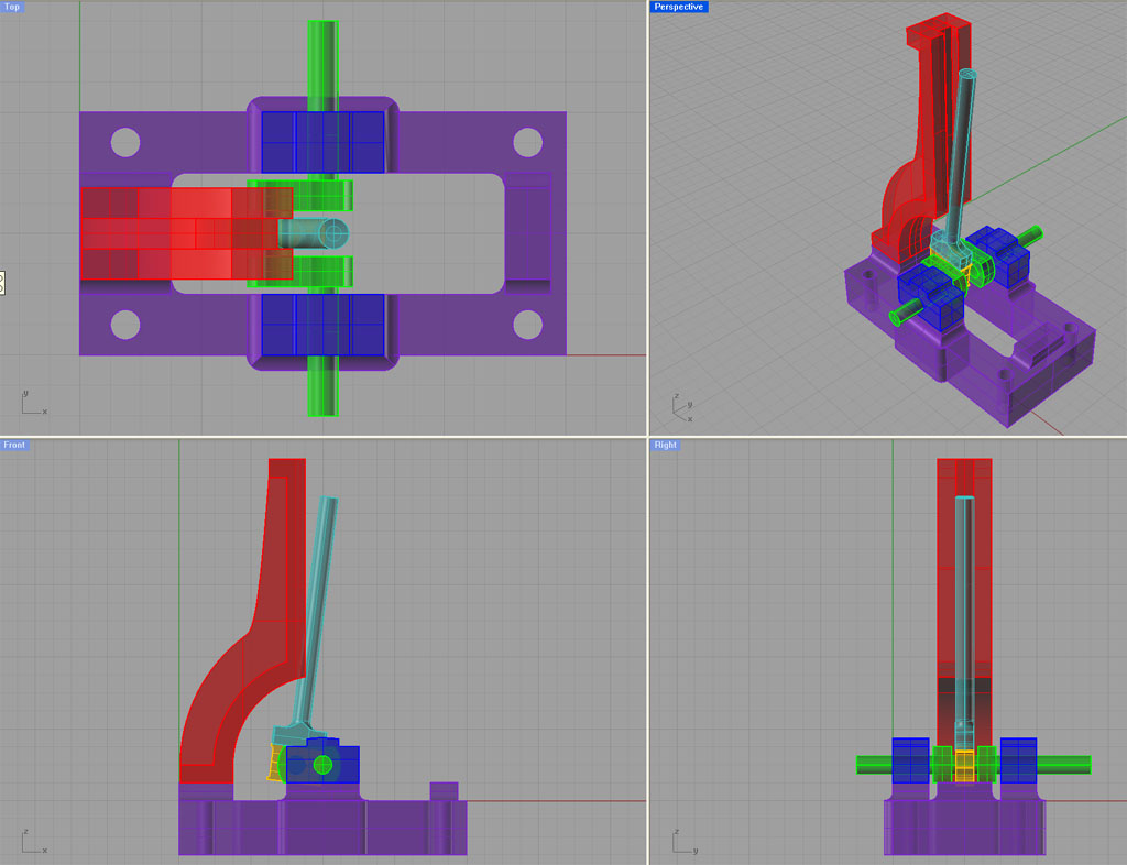
I've been slowly working on a Rhino 3D model of a steam engine similar to a Stuart Turner No.1. I was inspired by the Engineman's (John Bentley's) naval brass version of the same steam engine. Here are a couple screen shots to show how far I've gotten:
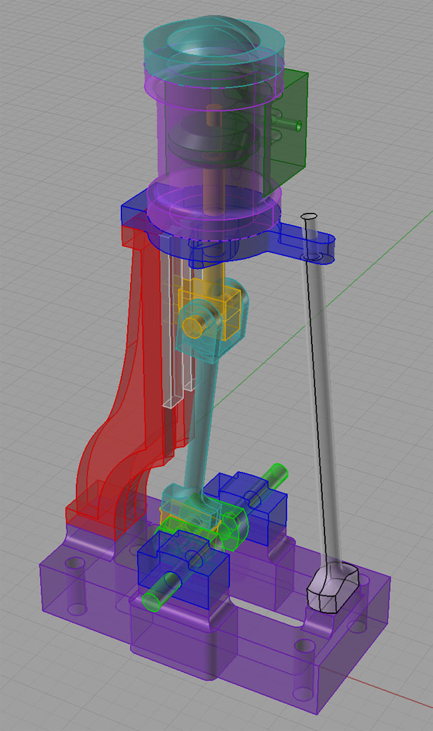
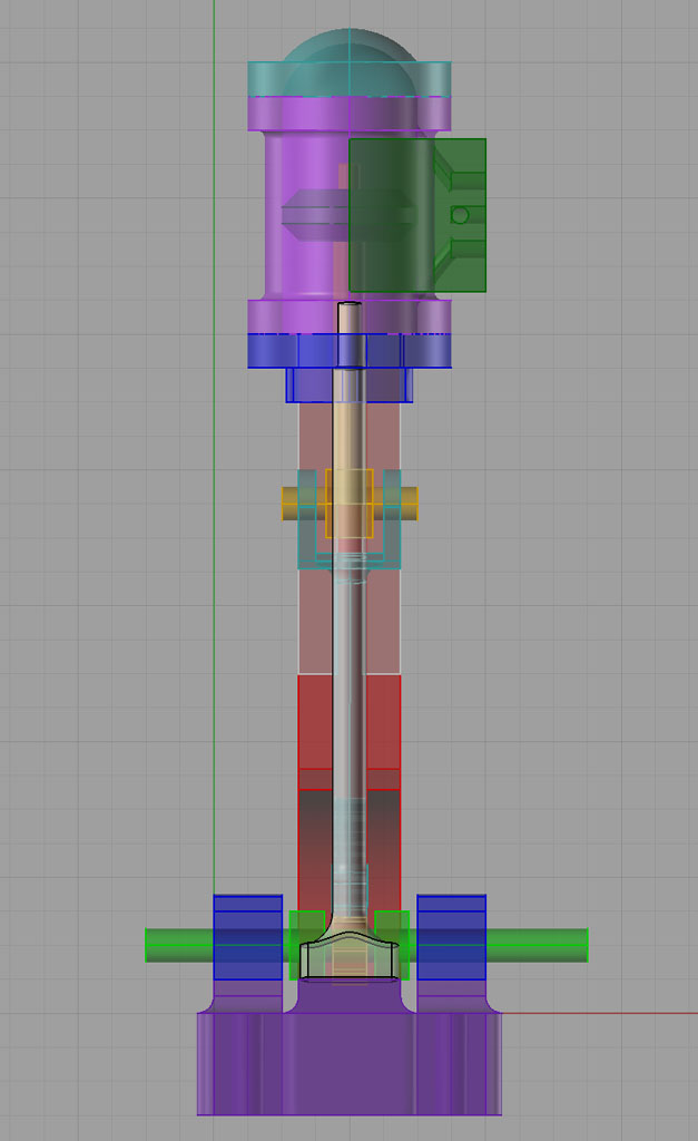
It's good fun doing these 3D models, and I sure am learning a lot about how a slide valve steam engine works! When I get all done I can scale the model to just about any size. If I like it well enough maybe I'll CNC one up down the road. It certainly would be challenging given some of the parts.
7/5/08
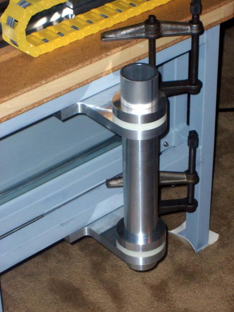
Preparing for the Column Pour on My CNC Mill Conversion
Since getting a new job in May I've been tied up for over a month before I could get back to my CNC work. I also had to finish up my little steam engine team build. I was able to carve out a little time over this Fourth of July three day weekend to make slight progress. I've basically epoxied a base plate into the bottom of the column along with a pipe that provides a bore for the big column bolt to go through:
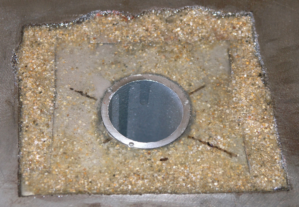
The surface tension works nicely to let me apply a fair amount of epoxy. I just want enough to hold the pipe solidly so that when I flip the column over start adding the E/G mixture from above it won't break loose. I'll let this cure all week and then hopefully tackle the column fill next weekend. I've decided not to fill the column all the way up. This arrangement will fill the bottom 10" or so and should add considerable dampening without in any way being a clearance problem. I would think this will really help the mill to perform better to have this much added dampening mass in the critical junction between the base and the column. More would be better, but I'm anxious to get on with the rest of the CNC conversion and there is a lot of work to do!
7/4/08
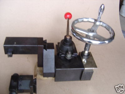
Indicating a 5C collet setup true
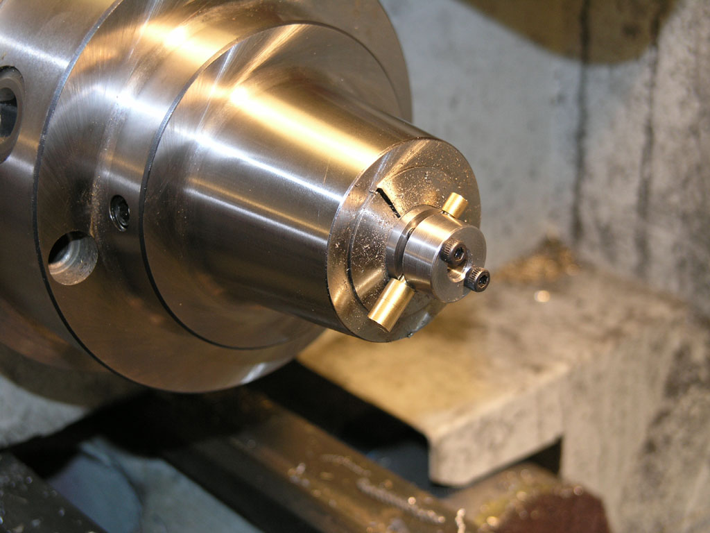
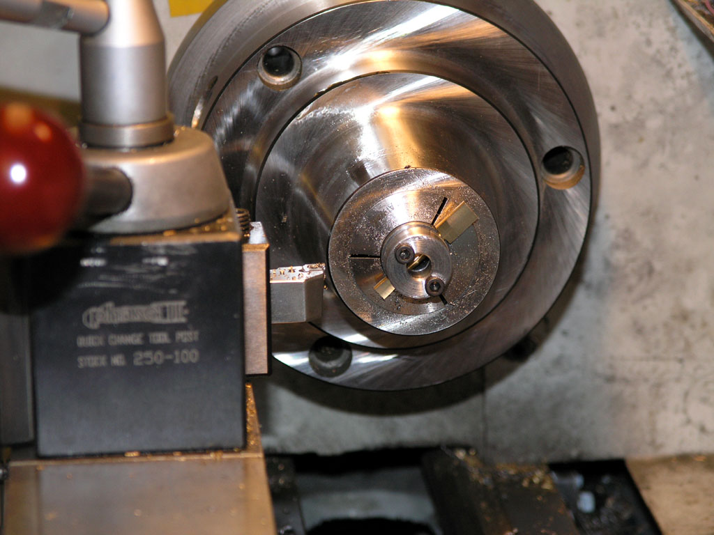
A company called Landis makes these 5C nosepieces that can be indicated true. Evidently they're intended for grinding but I can't see why the idea wouldn't work well for a lathe too:
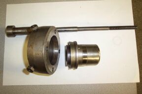
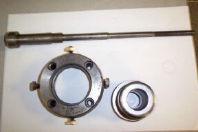
As you can see, there is a 5c nosepiece that rides in the collar. The collar has 4 set screws to adjust the nosepiece until the runout is zero. The drawbar holds everything in position, and the set screws ride in a groove on the nosepiece so nothing can fly loose. Seems like a neat setup that would not be hard for a machinist to build. I got an air collet closer off eBay, and I will be tempted to make one of these to go with it.
6/29/08
Bob's No. 1 Has a Con Rod Interference Problem
I was taking another gander at the magnificent photos on John Bentley's (The Engine Man) site when I decided to have a go at modeling a similar steam engine. Bentley's engine is loosely based on Stuart Turner's No. 1, so I thought i"d call this design exercise "Bob's No. 1" as well. It's amazing how much time you can spend on one of these and how neat they turn out. I got this far after about 2 hours:
I've got a little interference problem with the connecting rod! I'[ll have to go back and rework the standard...
Here are some more views:
I reckon this one will take a solid 12-15 hours to really finish. When I'm all done, I hope some day to make one of these via CNC.
6/14/08
Gang Tool Your Mill as a Vertical Lathe
As you know, I am a big fan of gang tooled lathes. How about turning you CNC mill into one in a pinch? This is a cool idea:
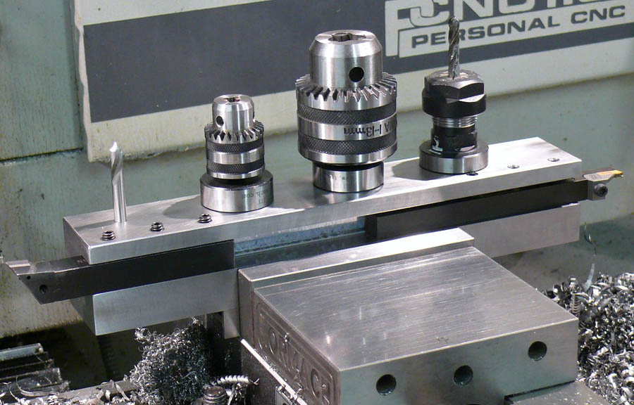
He's using his Tormach Tooling System holders with a slide mod--the Weldon-style flat. Presumably he can pop them back in the mill any time...
This rig is being used on a Tormach CNC mill. There are a few issues the builder mentioned:
I understand the first 2, but not sure about the 3rd. I would think it would be pretty easy to trick a CAM program capable of gang tooling into dealing with this arrangement. A bigger problem I would think is the need to load each part blank individually before turning it. Even a pretty simple CNC arrangement can feed the work through the spindle pretty easily. Still, if you just need to make a few short pieces, this would be a fast way to do it. I think I would add some means of registering the gang plate to the vise repeatably.
Tormach is selling a 7x14" Asian Mini-lathe they call their "Duality Lathe". The idea is to drop that onto the bed of the mill attach the tool to the spindle (with the spindle switched off, of course!), and go at it that way. It seems expensive and awkward to me compared to something as simple as this. The advantage of the duality I could see would be tailstock support and the potential to feed material through the spindle. On the negative side you have to manhandle the heavy little sucker onto your table, get it aligned so it is "trammed" to the table, and you're going to be swapping tools for every operation. I just can't see spending the kind of money they want for that "solution" when you've got the possibility for something like this.
5/31/08
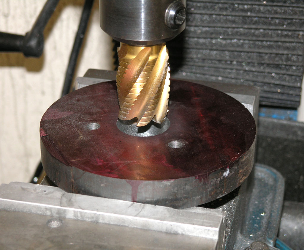
Use a Corner Rounding End Mill as a Form Tool
I just came across another great idea from the Widgitmaster, a regular CNCZone contributor who does amazing work. The latest involved bellmouting (radiusing) the ends of some tubing to make a swing arm for the controls on his new CNC router. Check it out:
Nice bellmouth created by using a corner rounding end mill as a form tool...
Here is where the tubing is going. What a professional looking swing arm!
It seems brilliant not to have to deal with hardening a piece of tool steel or laboriously grinding out an arc when there is likely a tool nearby already perfectly set up to do the job!
5/26/08
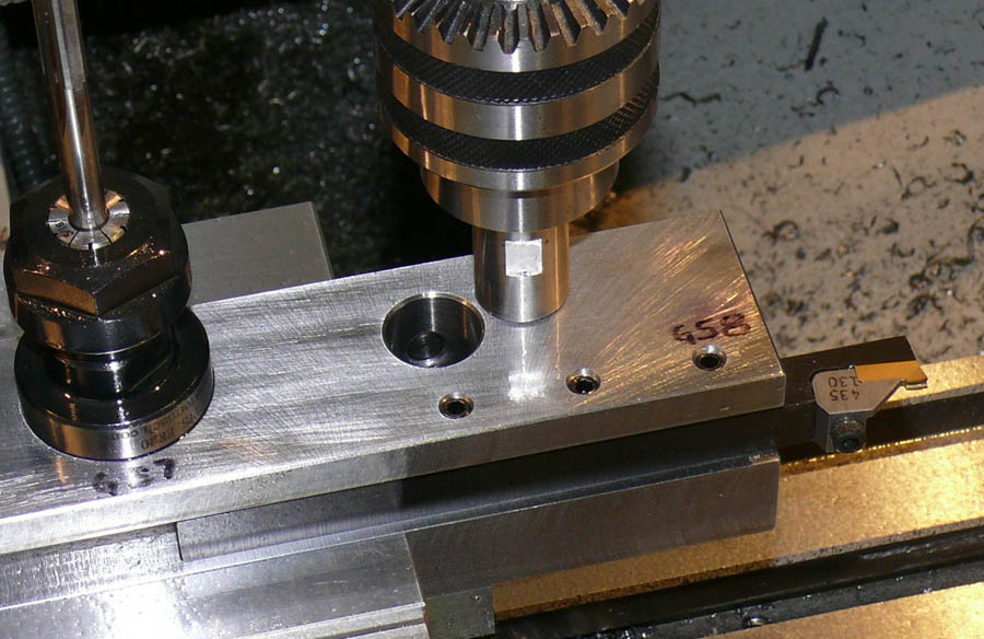
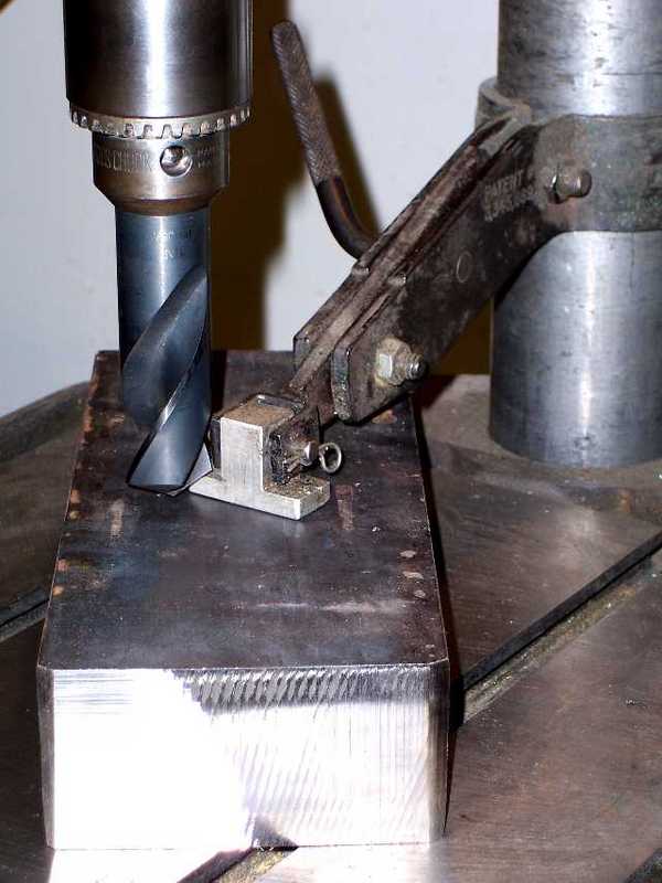
A Handy Rounding Over Fixture
Rounding over involves using a pin so you can rotate a workpiece close to a milling cutter to round over one end. As part of my Team Build for a little Elmer Verburg steam engine, I had to round over a bunch of connecting rods on the small end. Here is the fixture I hit on after looking over the bits and pieces in my shop:
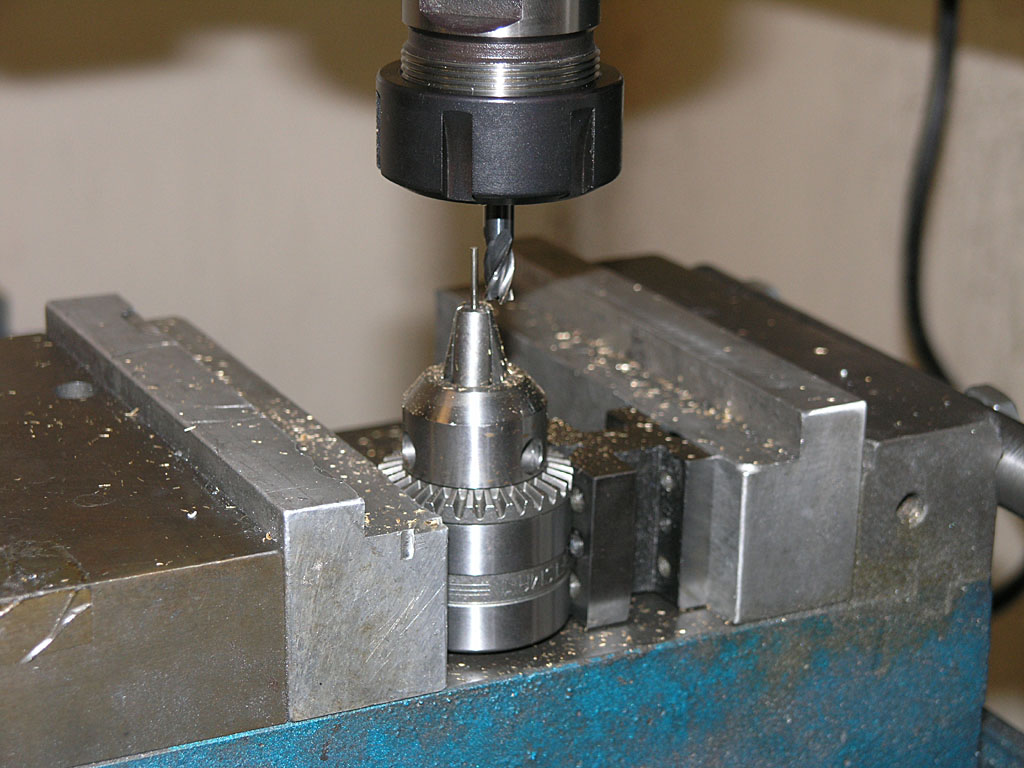
Here is my rounding over fixture. Take an unused drill chuck, a v-block, your mill vise, and an upside down twist drill of appropriate pin size. This assembly operates at a convenient height for my Kurt vise. I've centtered the pin relative to the milling cutter on the X-axis. Y is far enough back not to cut so I can get the part in place before starting the mill. It pays to keep track of this location for subsequent parts!
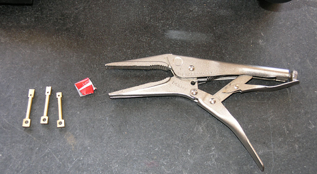
I'm going to use that little bit of aluminum soda can to make sure I don't damage my con rods holding them with the vise grips....
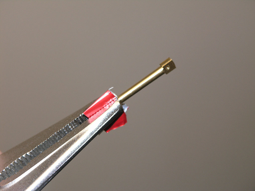
We just clamp the big end using the soda can as protection from the vise grip's serrated jaws...
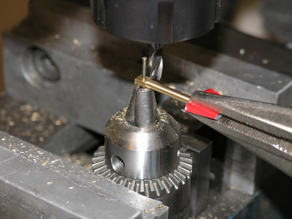
Place the small end on the pin of the fixture. I am using a 1/4" 4 flute end mill running at my mill's fastest speed...
I work the con rod from right to left because this ensures I am not climb milling. If I go the other way, the end mill tries to suck the work in and also tries to pull it up. I'm feeding about 0.015-0.020" per pass using the Y handwheel to feed.
There's the rounded over end. I'll give that little bump near the bottom a little file work to clean it up...
Here is my filing rig, a gunsmith's Swiv-o-ling vise and a needle file. I clamp it to my tool grinder table because it's a comfortable height to work on while standing....
here are the finished con rods. Not perfect, but not bad. This is about 2.5x magnification. They look even better to the naked eye..
5/18/08
Souping Up a Drill Press
For some reason I came across several interesting drill press related articles today, which prompted me to put together a page of ideas for souping up the lowly drill press. Mine could certainly use it. The idea was to collect all the things I've noted over time that could be done to make a drill press more productive to use. Check here for the new page. Here's just one example:
Cam-action table clamp on a swing arm...
5/17/08
Great Spindle Indexing Feedback: Thanks!
My spindle indexing note below seems to have really gotten the juices flowing for a number of readers.
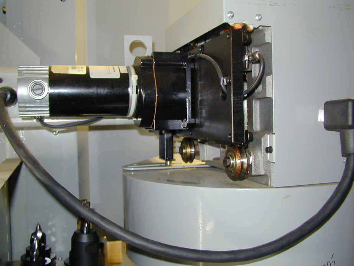
First, thanks go to Peter Tsukamoto of PT Engineering (my dream--a machine shop in Hawaii). While I've been thinking of C-axis ideas off and on for some time, Peter rekindled that interest with a series of notes. He re-raised the disc brake idea, which got me looking for the thread I'd seen in CNCZone again so I could share it with him. We've had a lively back and forth about the virtues of my two motor idea versus just biting the bullet and putting a real servo drive in place of a spindle motor. Peter does some cool work, retrofits machines, and has built some really neat capabilities into some of his machines. See for example his YouTube video of his Accuslide lathe cranking out parts:
Peter points out that you can buy brake lining material, cut generic square pads that are easily replaced, and machine your own caliper very quickly off a CNC mill. Another great one from Peter is an idea to converted a 3-phase motor so it is "vector rated". Vector rating let's you run the motor over a broader range without overheating. He suggests the main thing to do is control winding temperature. Start with an ODP open drip proof motor and machine an end frame to hold a high perf fan with temp sensor. This will keep it cool when needed and throttle air flow down when cold to reduce dust build up. If you run too fast (you can "overclock" with VFD and vector drives by increasing frequency to more than 60 Hz) the motor can overheat, and especially the spindle bearings, and if you run too slow there isn't enough airflow from the shaft fan. An electric fan with sensor means the fan isn't limited to shaft speed.
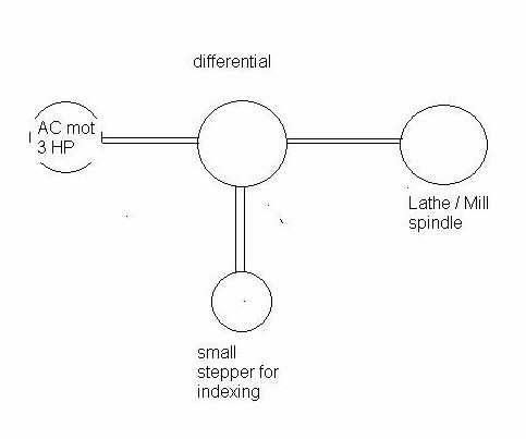
Next, Cor van der Jagt from the firm idaps.nl in the Netherlands wrote about an idea to isolate the motors in a 2 motor situation. He suggests using a differential to decouple the motors:
Lastly, Rus Crespo suggests mid-80's GM front wheel drive vehicles for brake calipers. He says he found a reman caliper for an 87 Chevy Celebrity for $18 and a new rotor for $12. You can hardly buy cast iron for that! The Gm calipers are a floating design, so there is only one piston and the caliiper floats relative to the rotor, so you have to use sliding caliper bolts to secure it. He goes on to suggest disc brakes from riding mowers if you need an even smaller size, or perhaps for g-karts.
The only other thought I've had is I'd be tempted to go with an aluminum rotor. It's not going to get the wear a real vehicle brake gets (at least not in my shiop!), and it would be a lot lighter. I machined an aluminum disc that came out very nicely for my 12" disc sander and it spins very well at 3400 rpm.
These are all great suggestions guys, thanks for chiming in!
5/16/08
Vector Drive Magic and Indexing the Spindle of a Lathe or Mill
I've been keeping an eye on vector drives for a little while now. Essentially, they are a "better VFD" to drive an AC motor with variable speed. Why better? Because they enable a wider speed range without loss of torque. I read a white paper by Reliance Electric that indicated you could expect a 2:1 range for a regular VFD, and a 4:1 range with a vector drive. In other words, run your motor at up to half speed without losing torque with a normal VFD, and 1/4 speed with a vector drive. Why does this matter? Because the speed range you need to cover the gamut of machining tough steels all the way up to aluminum and soft materials is huge. To span a range of 100 rpm all the way to 8000 rpm (still nowhere close to what a lot of CNC's run today) takes an 80:1 range!
That's why you need gear changes, back gears, step pulleys, variable pitch pulleys, or a host of other mechanical transmissions used on different machine tools. But those transmissions are a hassle to deal with too, especially if you want to build your own machine, or radically alter the performance envelope of you spindle.
So it was with some interest that I came across a Sumitomo Vector Drive spec. I guess a good vector drive these days has more range than Reliance gives them credit for. A sensorless drive is one you could just hook up like any VFD, and Sumitomo claims a range of 120:1 for their HF-430 unit in sensorless mode and that with a speed accuracy of 0.5%. But it gets even better. Add the encoder board and put a suitable encoder on the motor and now they're claiming a range of 1000:1 and speed accuracy of 0.05%! That's starting to be quite a range, and these drives have gotten a lot cheaper over time. I came across this particular one in an eBay buy it now for $249 for a 3 HP unit.
The only thing missing from it seems to be true servo operation, or at least a means of parking the spindle at a known location. True servo operation would allow the spindle to be indexed to any arbitrary position. You can imagine that would be handy if you wanted to set up your lathe spindle with a 3 HP motor (or more) and treat it as a C-axis. Index to a location, put an air powered spindle on your CNC gang slide, and you can suddenly drill a bolt circle for a flange under CNC power. A parking position would make implementing a tool changer for a mill a lot more feasible. Park the spindle in a known location and the "dogs" on the toolholder are properly lined up.
I got thinking about this, searched CNCZone, and didn't see an awful lot of help there. Then I realized I was just making it too hard. Why not just lash up a suitable stepper or servo and use it for the indexing operation? First, I am envisioning a system that does not be able to continuously machine as the axis rotates. It is a pure indexing system that indexes a position, locks the spindle, and then performs the machining task.
Second, this implies to me a spindle brake. That makes me think of a disc brake, and I've written about that in this blog before. So I envision a rotor with a disk brake caliper to look the assembly. Probably use a motorcycle-sized rotor/caliper to keep the weight from getting too crazy. There's a CNCZone thread where a fella did just that and controls the brake with an air solenoid. I would think if you can find a scrapped bike the disc rotor and caliper would be very cheap to buy.
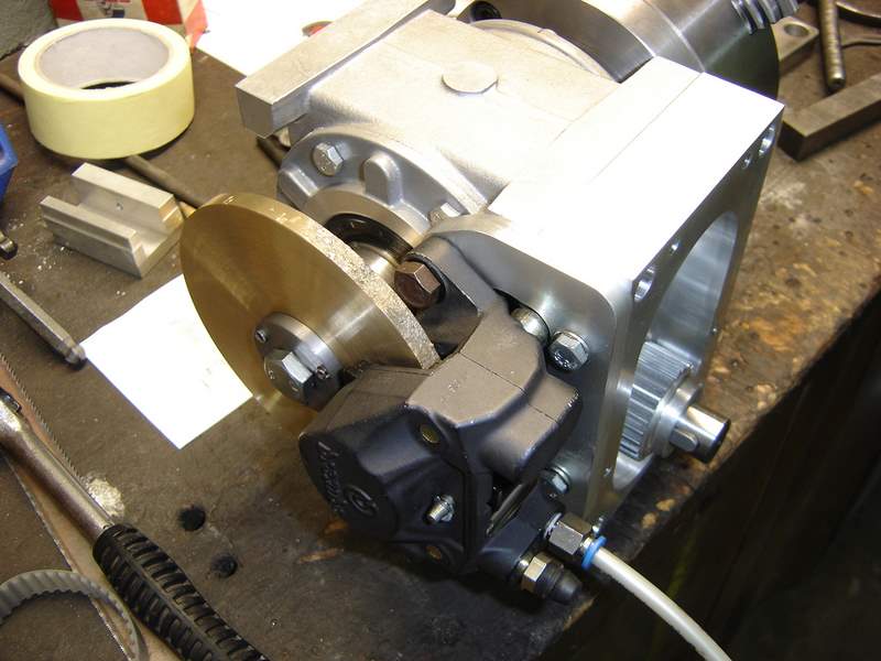
Using a disc brake caliper to lock an indexer...
Third, how then to index? Again, it seems to me the easiest thing is to arrange a second motor to do the indexing. Seems to me servos are designed to run at the kinds of speeds these spindles turn at. Just bought a nice one from Homeshopcnc that'll do 4500 rpm, for example. So we make sure that we can run one motor or the other BUT NOT BOTH electrically. We freewheel the servo when the spindle motor is going, and freewheel the spindle motor during indexing. Why a servo? Well because we can put the encoder onto the machine's spindle (not the spindle motor!) and let it sense the true motion and soak up any backlash to increase accuracy. There won't be much anyway if we use a toothed belt drive. If you prefer, a decent sized stepper is cheaper still. You'll want to groove the toothed belt else when the spindle motor runs it'll scream like a banshee, but that's easy to do too. So, we need to add a toothed belt pulley to the existing spindle motor pulley stack and drive it with a suitably mounted servo or stepper.
Let's think about the motor interlock. I would want a failsafe such that their is a contactor or other high reliability way to ensure there is no power available to whichever motor is not in use. I'd probably use an input pin to trigger indexing mode, and another to trigger the spindle brake. Note that we really need to completely cut off the power to the stepper/servo indexer when not using it or it'll try to force the spindle to its desired position causing all sorts of trouble. While we're at it, this should be a tri-state where we have just one of the following modes:
- Spindle mode: Give the spindle drive (VFD or Vector) the juice and let it operate the spindle normally. You'll want spindle on/off, forward/reverse, and speed control. The brake and indexer are disabled.
- Indexing mode: The spindle and brake are disabled. The Gecko (or whatever drive) to the indexing motor is energized. You can command motion from the C (or whatever axis you set it up as in Mach 3) axis in your g-codes to index. Light machine would be possible without the brake, but probably not recommended.
- Brake mode: The spindle and indexing motors are both disabled. A compressed air solenoid energizes the brake, locking the spindle in its current position to allow machining. Note that we may want to slightly overlap the indexing and brake modes to make sure that the indexing motor holds the spindle in the correct position until the brake is fully locked.
I'll have to think about how exactly to implement such an interlock, but it sure seems like this does the trick relatively cheaply and easily.
5/15/08
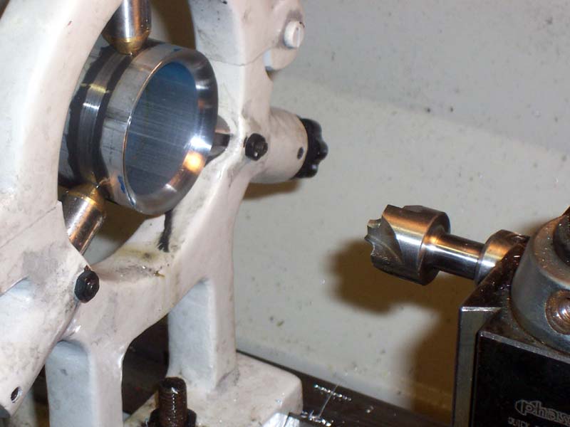
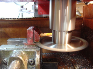
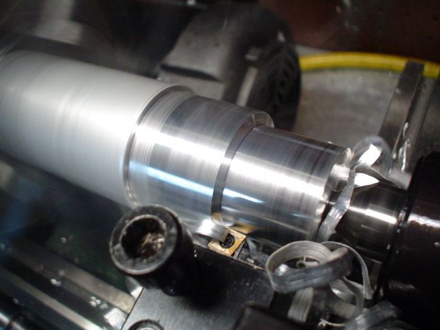
Royal "CNC" Live Center
Recently I was making some connecting rods for the Team Build I'm in, and discovered my existing Royal Live Center was not going to work. You can see the problem in this photo:
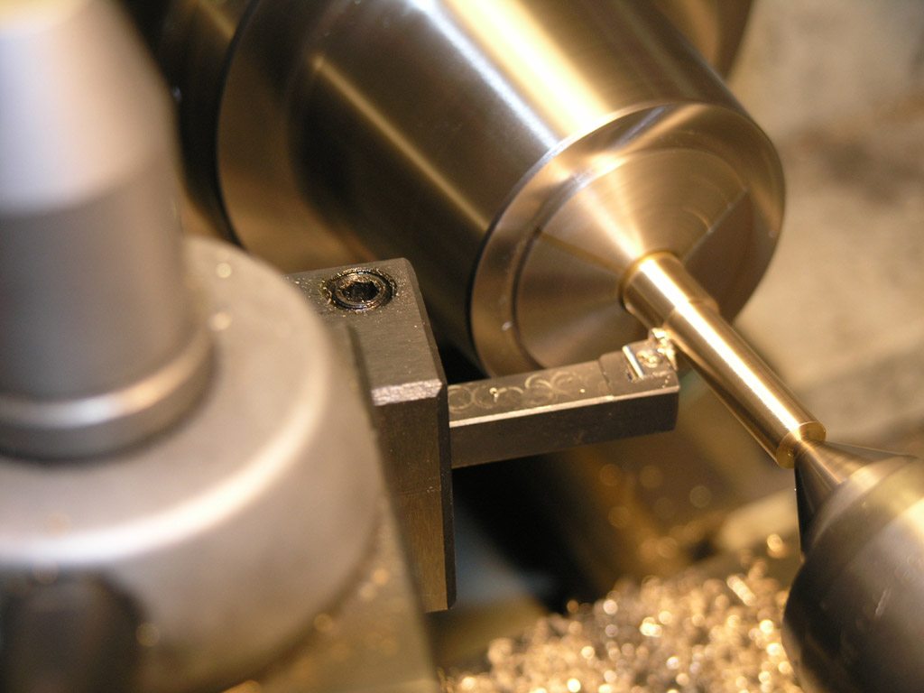
Not enough clearance between collet and live center: Doh!
I've got my tool hung way out and angled to clear the center, but I still can't really cover the whole length of the workpiece. I wound up not using the live center. No harm done, but I did have to be extra careful and take lighter cuts and I did screw up a couple parts while I was working out what I could do. Along comes my latest Enco catalog with something they're calling a Royal "CNC" Live Center on sale:
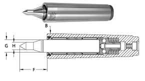
The "CNC" live center...
Note the little extended tip. That little goodie would've given me the extra clearance to make this job work. The CNC model is also spring loaded to automatically maintain proper pressure.
My existing center is also a Royal, and it works very well, so I'm tempted to order one. Still not very cheap even on sale: regular price is $215 and the sale price is $172.
5/10/08
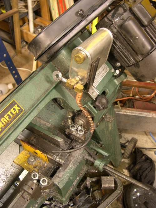
Bandsaw Drip Oiler
I thought this was a clever idea from Evan over on the HSM board. It's a drip oiler for the horizontal bandsaw. When the saw is down and cutting, the nozzle is below the "water line" of the coolant, and dripping proceeds through an adjustment valve. Raise the saw and the nozzle rises above the line so the gravity feed stops. I use my bandsaw primarily in the vertical position these days, so it wouldn't help me, but it might be just the ticket for a little cutting oil to increase your blade life if you use these handy saws for cutting stock to length.
5/05/08
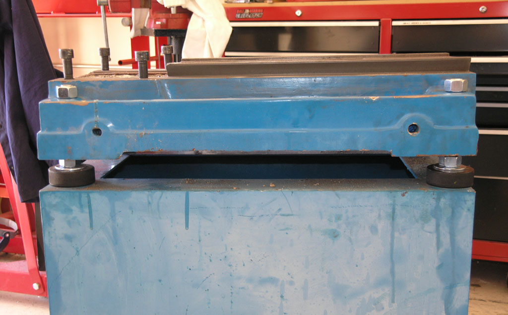
Hockey Puck Leveling Feet on the Mill
I finished this project a couple weeks ago but didn't get the pix posted. Full details on the page describing the process (scroll it's in there!), but they came out real neat:
One Good Machine Can Make Another
That's the thing about a CNC mill. I've watched folks get the basic mill going and then use it to make all sorts of other things, including even better machines. Take Bob "Bird E" from CNCZone. He started out converting a Sieg X3 and did a real nice job (pix on his personal web site). After a little while, he got a bigger mill, an RF-45 similar (but a little smaller) to my Industrial Hobbies mill. Now he made all his conversion parts on his Sieg X3 using the CNC. They came out really nice:
How'd you like to make this curvaceous piece manually with a rotab? Not me!
This will be a fun build to watch. I read on the 'Zone that he just got an automatic Bijur oiler, so he's probably planning an automatic way oiler like mine.
The Age of CNC as a Commodity
What happens when custom CNC machines are so easy to build that anyone can create a purpose-built machine? Intriguing thought. All sorts of things would be possible, and very useful!
There's a fellow over on CNCZone who has built a special machine for resawing wood into 1/8 and 1/16" sheets. Very neat, cost him about $300.
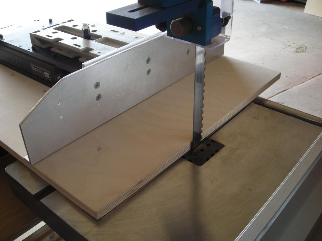
The CNC portion is on the left. It moves the workpiece through the bandsaw blade both to feed and set depth of cut, so 2 axes...
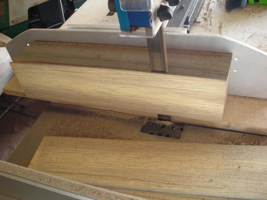
Here it is in action. Note that the lower board doesn't move and the workpiece is glued to the aluminum fence...
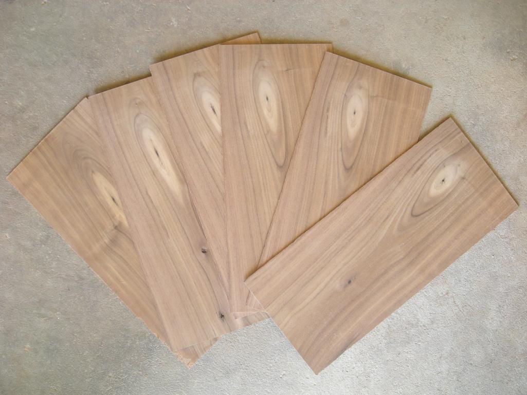
Nice sawn blanks, eh? There's a YouTube video on CNCZone. Check it out!
Bought a Set of Servos and Gecko Drives from HomeShopCNC
After reading a note sent to me by Peter Tsukamoto, I got inspired to take a step of some kind on the mill to move this conversion forward. Peter started with a Unimat lathe 30 years ago and today he owns a full machine shop in Hawaii. Guys like that are always an inspiration to me, so I try to listen carefully when they have some advice for me. In Peter's words:
See if you can get your CNC mill going as a priority. It will open up new vistas in a way you cannot believe. It will accelerate any project you work on. Make them way more enjoyable too.
He makes a lot of sense there. Every time I perform a manual machining operation on my lathe or mill I think about what the CNC equivalent would be. In almost every case I could do the job much faster, more easily, and often better with CNC. There's a reason it took the industry by storm years ago!
A couple things have been holding up my progress. First, I've been spending a ton of time lately on a Steam Engine Team Build that has involved creating some tooling and a number of other things. The other problem that was distressing me was that I had misplaced the Industrial Hobbies CNC conversion kit somewhere in my house. I'd been looking for it off and on for days, and the number of places it could be was dwindling. After spending 45 minutes in the garage shifting things around and checking every last possible hiding place underneath all the junk, real panic set in. Paraphrasing Conan Doyle's Sherlock Holmes, when you've eliminated all the possibles, you have to start considering the impossibles. Eventually I discovered that my kids had pressed the two boxes into service to create a stand for their Karaoke machine. They were hidden underneath a black table cloth to make it even harder. I heaved a mighty sigh of relief after making that discovery!
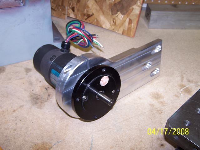
So, having located the components, I decided to take another step and ordered up a set of servos and drives from HomeShopCNC. I also looked at Keling as another source. HomeShopCNC was just slightly cheaper on Gecko drives, and I liked the nifty anodized housings for the encoders:
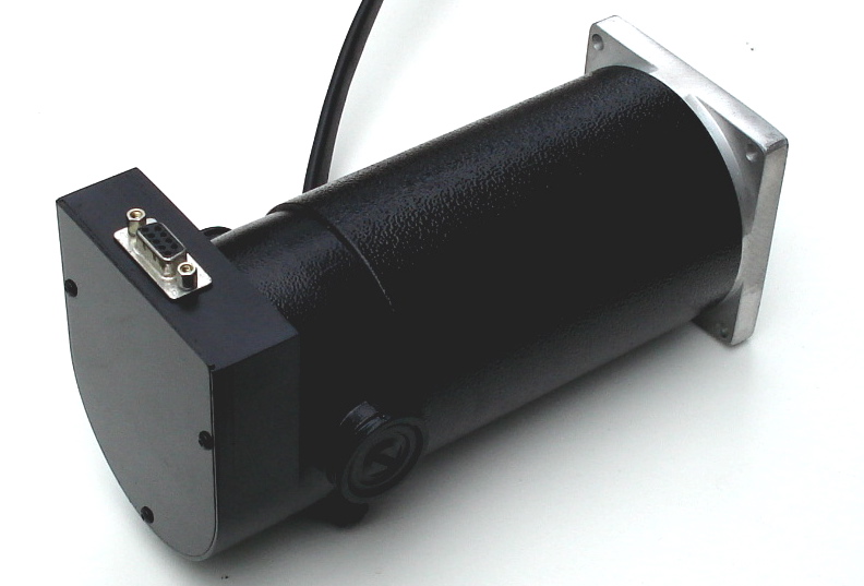
I like the nifty anodized housing for the encoder...
These are 850 oz in servos, and Keling had a bigger model at a whopping 1125 oz in. Why not just buy the bigger-is-better plan? Well, because there are trade offs. It's worth noting that the standard IH CNC kit comes with 410 oz in on the X/Y axes and 648 on the Z--that mill head is heavy! Their heavy duty kit looks to me like is substitutes the bigger Z servo on the X/Y axes. Either way, I should be fine with 850 oz in. Now here is the rub. The big Kelling 1125 oz in servo peaks out at 3200 rpm whereas the 850's I got are spec'd for 4200 rpm. I don't know if I'll ever get to use the extra rpm to increase my rapids or not, but bigger servos are often slower and the same is true of stepper motors. I think these 850's will be a decent compromise and they'll give me some room to experiment on my feeds and speeds. If the Z gives me any trouble I figure I can build a counterweighting system with some gas springs and radically reduce the force needed there too.
While I'm talking about alternatives, I should mention that I did some serious looking around for an alternative to the Gecko drives. Why? Customer Service. That's got to come as a surprise because Gecko has some of the best customer service reputation in the industry. The trouble is, I ran afoul of one of the counter examples of that. My GRex for my CNC lathe project has been a disaster. The good news: it was very easy to get it working, and I like the idea of not relying on the parallel port. In theory, it could save me a lot of trouble, especially since I had envisioned a fancy control panel for it. The reality? The device has never lived up to its original promises. It has had teething troubles since the beginning, and most of it has never gotten fixed. There are problems with 3D profiling on the mill that make it a questionable solution there, and the device doesn't support spindle indexing on the lathe, which is a requirement for threading. What good is a lathe that can't thread? Many promises were made over time about this being fixed, and we're talking a span of years. Unfortunately, it has never panned out. Gecko blames it on the firmware and says it isn't their fault. I think that's silly, and it certainly was not the story at the outset. I sent Mariss a note offering to trade my perfectly good GRex for a set of 3 of his cheapest servo drives (which combined were less than the GRex cost), and explained my problem with the GRex. I never even got a response back from Gecko. That's just not good customer service in my book, despite their stellar reputation.
So how did I wind up buying another set of Gecko drives anyway? Here's the rub--who else is there? Rutex is in an odd state. The parent is Australian, and the designer has gone missing there last I heard. Reports vary on whether the boards can be gotten here though the US distributor says yes. Last thing I want to deal with is another strange situation with one of these boards though the Rutex has a lot of advantages over the Geckos on paper, and there are certainly those who swear by them. I also looked at the UHU family of servo drives. These look to be excellent, but so far they are either awfully expensive if you buy one already built, or you deal with cobbling together a kit. Frankly, I was tempted to go the kit route anyway, just to avoid Gecko. I enjoy building electronics and I'm pretty good at it. The trouble is, Peter's words kept nagging at me. How much would it set back my conversion to have to build and debug 3 servo controller boards? So I got the Geckos. They were cheap when bought with the servos anyway.
Still, it wouldn't have taken much to get me to buy something from someone else. I guess that's the power of customer service. Given his reputation, I can't understand why Mariss wouldn't do something for me. Oh well, I sure hope these new drivers are flawless or I will build the UHU boards.
I'm going to update my To Do list for the mill to a finer level of detail, finish that Team Build, and then try to see how much progress I can make on the mill conversion.
5/042/08
A Neat RCMT Profiling Tool for the Lathe
Thanks to BogStandard over on the HMEM boards for making me aware of these nifty profiling tools. They use a round RCMT carbide insert: RCMT 0602 MO. I got mine from RDG Tools in the UK, and they were happy to ship via Royal Mail to my shop here in California.
You can compare surface finish against my CCMT tool with a new sharp CCGT insert. The RCMT wins hands down!
Give Your Parting Blade a Tune-Up, Plus Turning With a Parting Blade
I use these little HSS steel parting blades:
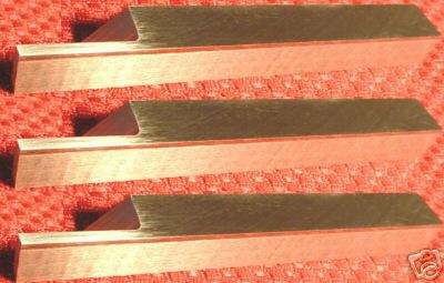
They're made on a surface grinder, though I buy mine on eBay from seller samsws, and are usually listed as "Cut-Off Parting & Grooving Mini Lathe Tool". The price for 3 was $16, and I've found they work great. You can just pop them into a regular toolholder. Not as heavy duty as the Aloris above, but they do make a much finer cut, so I use them for smaller diameters.
While I love the little parting blades mentioned above, I find they benefit from a little "tuning up." Here's how I do the tune up:
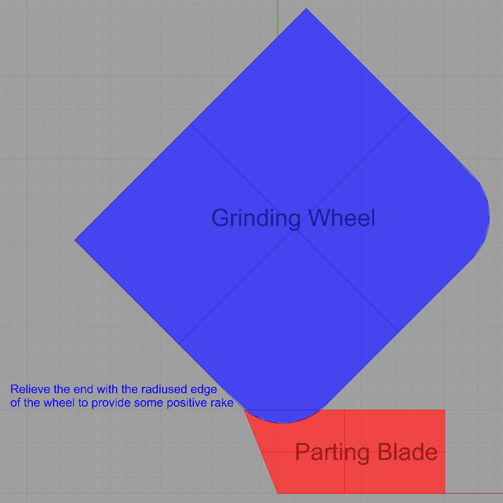
First, use the radius on the edge of your grinding wheel to put a little positive rake in the blade. This greatly reduces chatter on a lot of materials. Easy does it, don't take too much off!
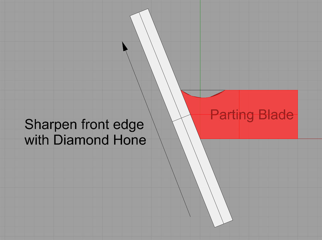
Next, take on of those inexpensive pocket diamond hones and use it to make the tool really sharp. I QCTP holder with the tool on its side on a flat surface, and stand the hone up on it's side. A couple of swipes as shown are all it takes to make the blade really sharp!

This last tip is not really necessary for parting, but I somethings use my parting blade as a turning tool, for example on my Verburg Steam Engine Team Build connecting rods. A radius like this is essential for such cuts. Put the radius on the side you'll be moving into the cut. The radius shown gives you a tool that can take shallow turning cuts moving from tailstock to spindle...
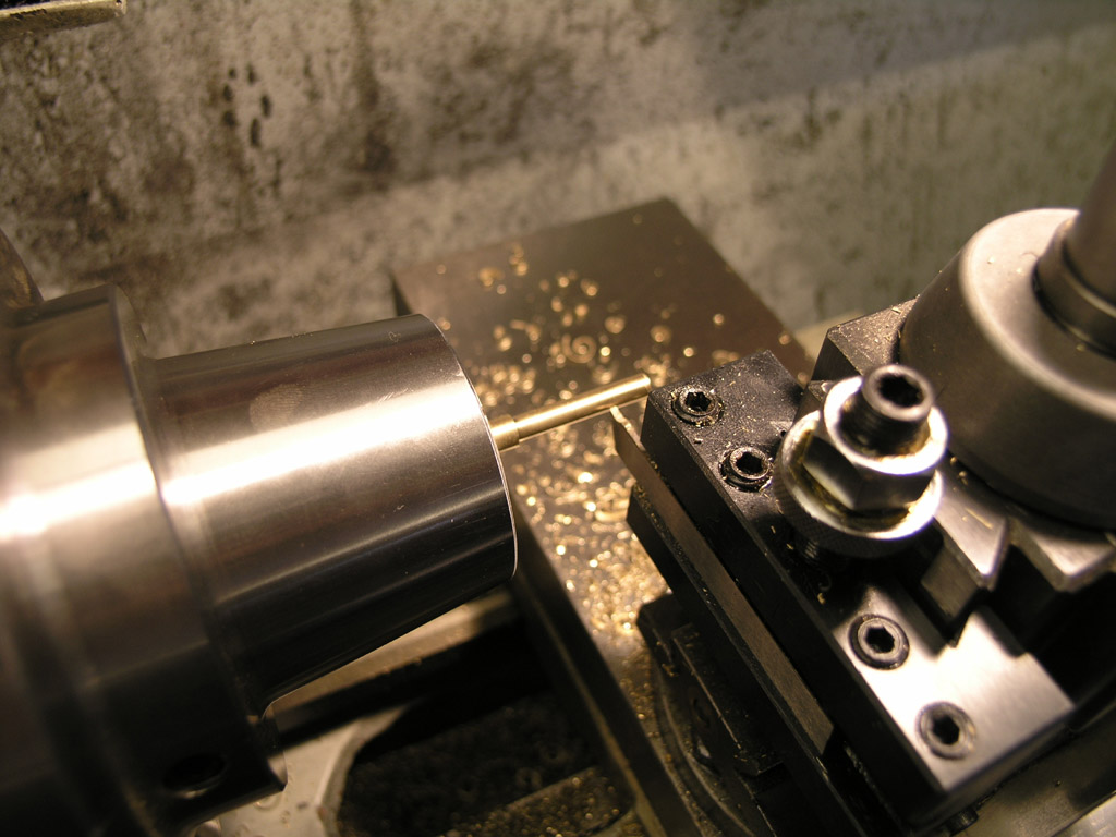
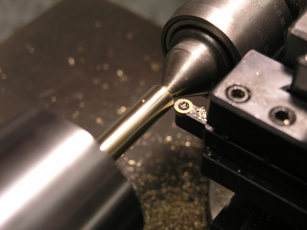
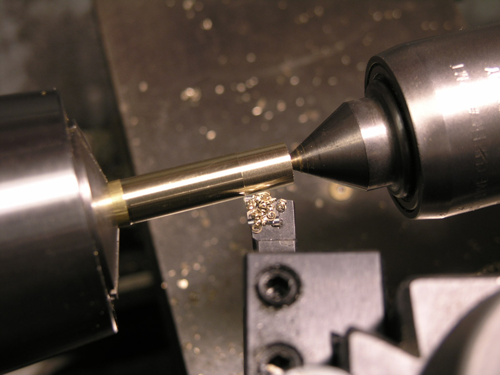
Turning with a parting blade makes it easy to get nice square shoulders if you need your smallest OD between two larger OD's. Here, we are about to plunge the blade and we'll be turning to the left shoulder that's visible. Don't try too much depth of cut. A sure sign of trouble is a build up of material on the part at the cutting point. Eventually something will break if that's happening--take a shallower cut! For this little brass part 0.010 to 0.015 on the dial (0.005 to 0.0075 actual DOC) worked well and gave a decent surface finish...
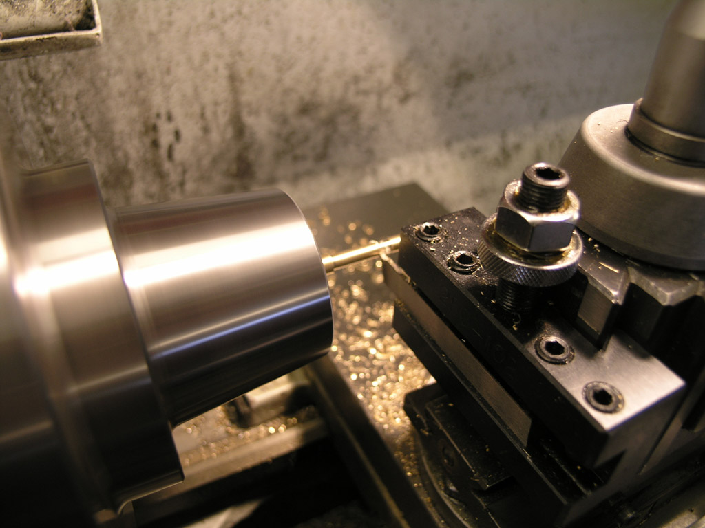
Here we are starting a pass. You can see the positive rake radius in these two pictures...

Nice square shoulders thanks to the parting blade!
More tips on parting can be found on my Parting and Cutoff Page.
How Toolchangers Work
Here are some great pictures, courtesy of Ken Shea, of the toolchanger on his Haas mill for those who wonder how one works:
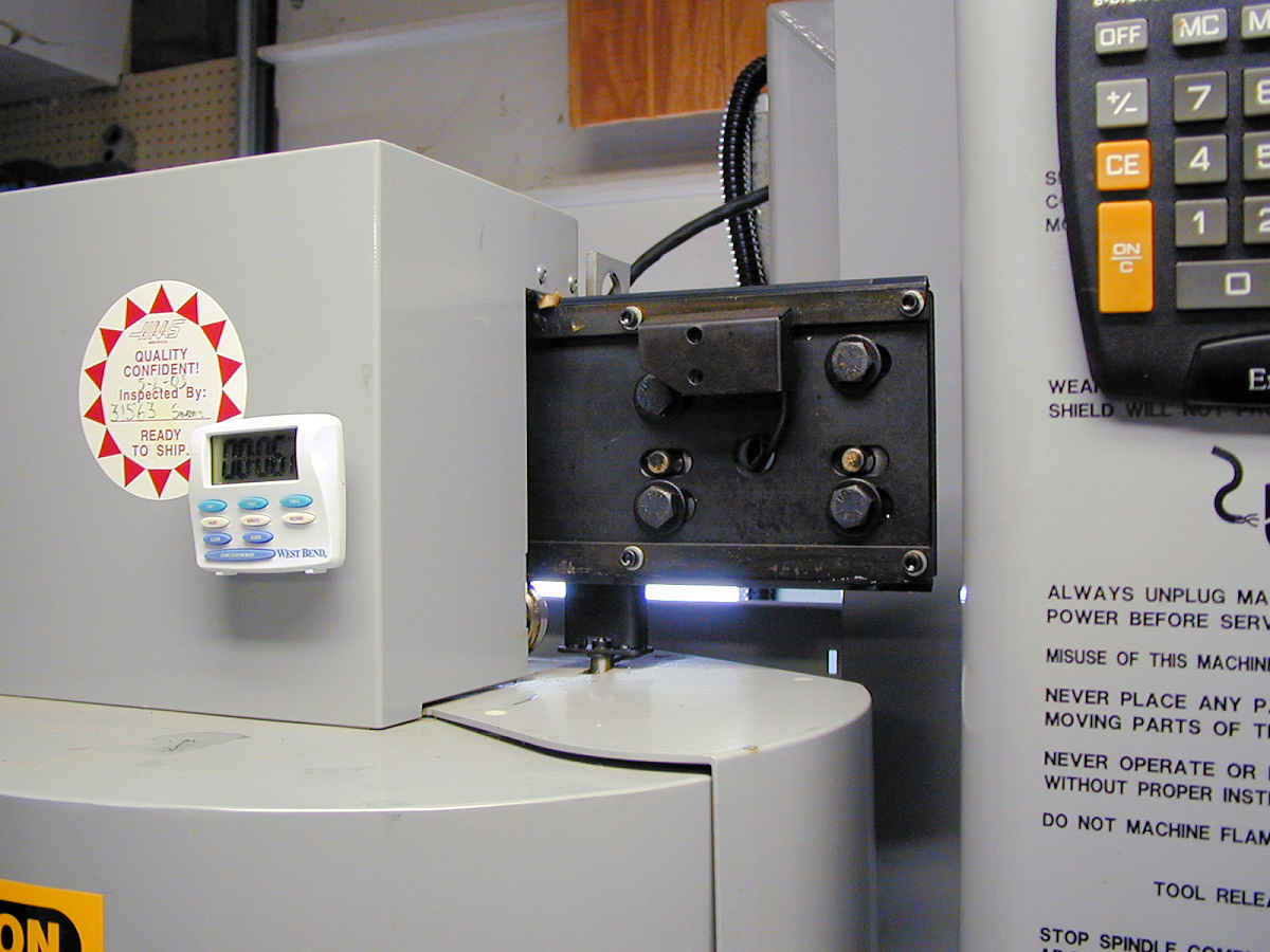
The changer travels on a V-Groove pulley sysem on this rail. You can see the spring-loaded door is linked to the rail so that it automatically opens as the changer heads over to the spindle...
A servo or stepper activates the motion of the changer. It wants to be fairly precise to position the tool properly on the spindle centerline...
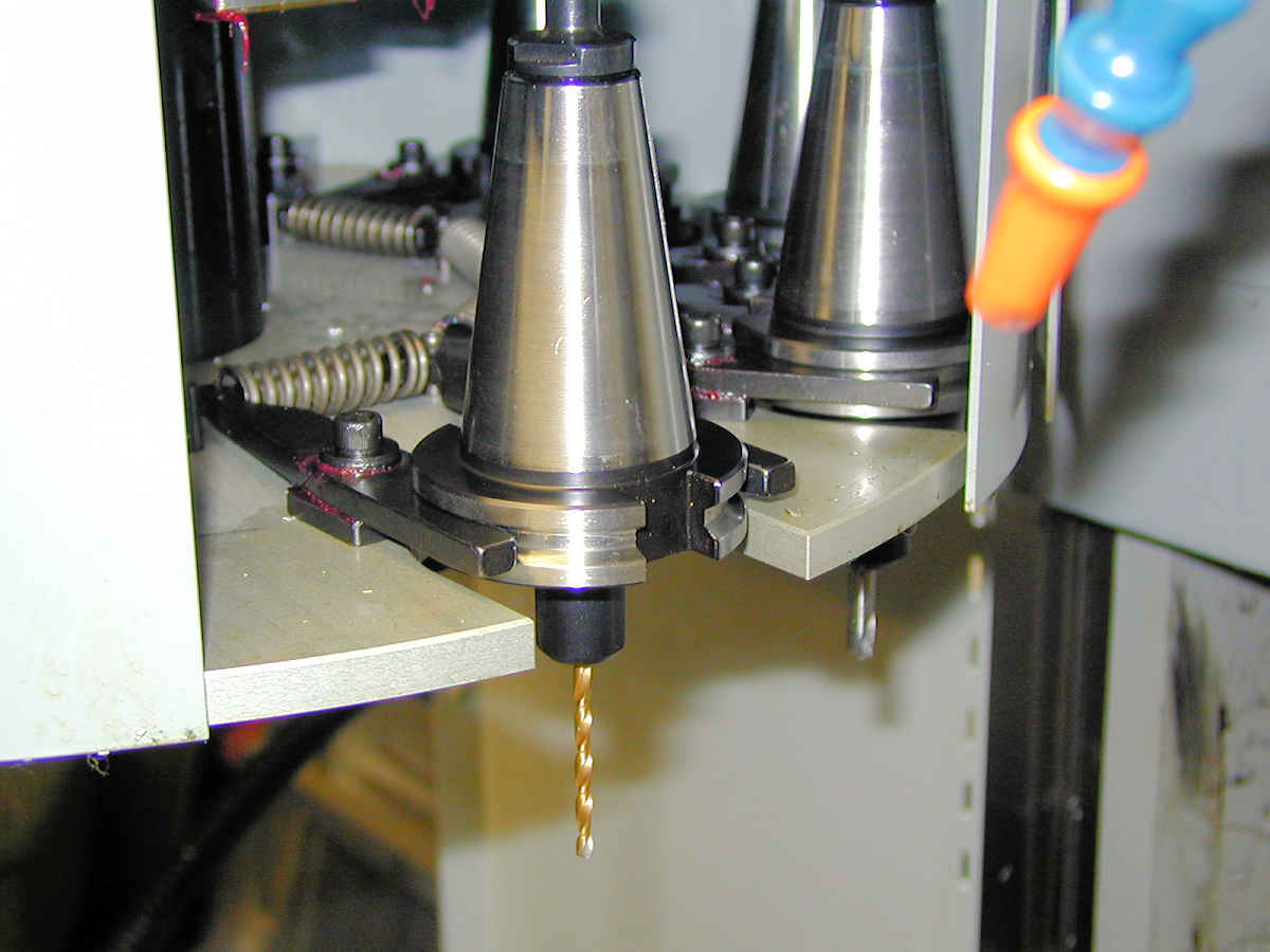
A look at the spring loaded clamps that hold the tooling. Another centrally mounted stepper/servo rotates this assembly to bring a new tool into position for the spindle to pick up. The little crossbar that the clamps pivot on has a tab that mates to the tooling slot to keep the toolholder aligned with the dogs on the spindle. The spindle itself would need to be a servo drive or other arrangement to index its dogs to the same position each time.
5/02/08
A Thimble Steam Engine
This little wobbler, courtesy of HMEM board, was apparently built from plans in the book, "Steam and Stirling Engines." It is from the article, "Thimble Power Plant", by James Senft. It has a 1/16" bore and stroke. The flywheel is 1/4" diameter the crankshaft is .020". It runs at about 20,000 rpm because it is so small.
4/30/08
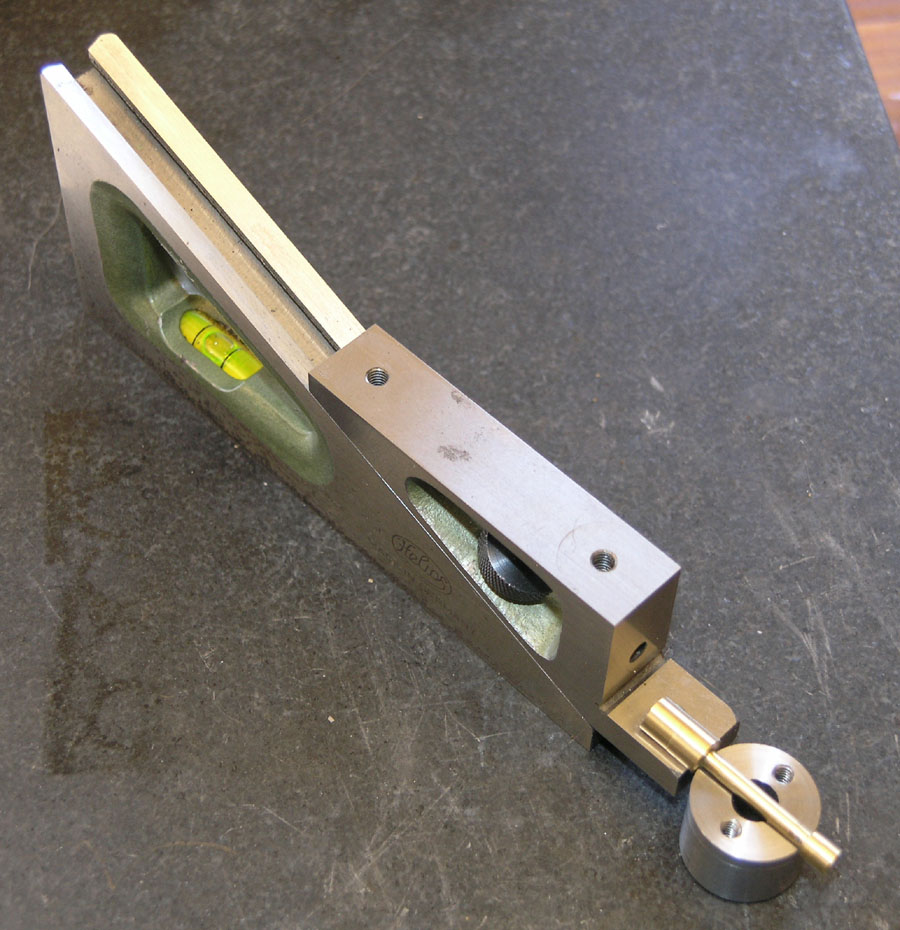
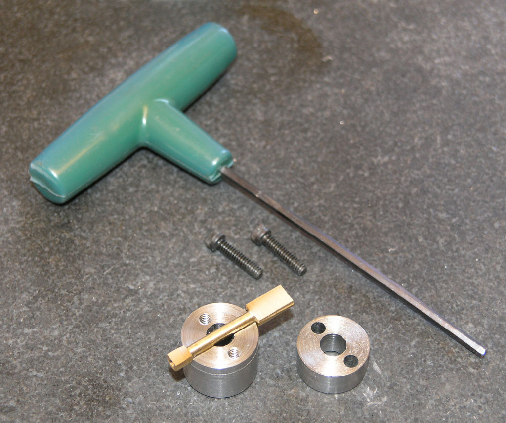
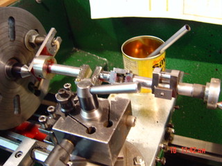
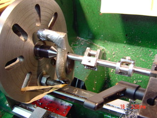
Finished My Button V-Block!
This is a handy little fixture for certain operations on the lathe. In this case, I made it to use for connecting rod work as part of the Team Build I'm participating in:
A con rod blank is installed and ready to be faced...
Facing puts the flats on the big and little end...
I use my Planer Gage to flip the part and do the other side...
Very handy little fixture!
4/29/08
Machine Age Design
I recently came across photos of this little compressor on a completed unrelated search. I've always loved the Art Deco/Machine Age style of design. Streamliner steam engines and other cool design motifs were common in the era. The ideal of this design style was to create shapes that looked as though they were moving very fast even when they were standing still. Hence they were "streamlined" and filled with sinous curves.
This marks the first time I've ever seen something that would be suitable for a shop, however. Isn't it nifty?
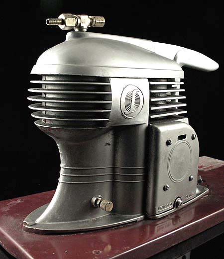
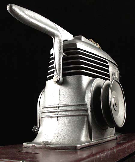
The compressor is made of aluminum castings and was sold in the 40's by a company called "Spray-It".
Model Engineering in the Jet Age
4/20/08
Robodrill Capabilities
The Robodrill is a small VMC that is interesting to compare to hobby-class machines like my Industrial Hobbies mill. I came across an interesting thread over on PM today discussing what they're capable of. According to Frank Mari:
- Drilling and tapping, no problem.
- Run a 3/8" endmill to full capacity.
- Run a 1/2" endmill to 50-60% of capacity.
- Forget 5/8" or 3/4" endmills except for light facing cuts on a workpiece you're sure cannot shift or move.
Interesting discussion. These parameters are based on trying not to break the pull stud which would wreak havoc on the spindle. The other interesting note is the comment that a Robodrill is much faster than a Haas TM-2, and the comments about the toolchanger: marvel of simplicity with no reliance on compressed air. The entire mechanism is powered by the Z-axis and spindle, and it's fast too! I'd love to track down more info on how it works. Might be just the thing to design for an HSM mill project.
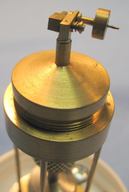
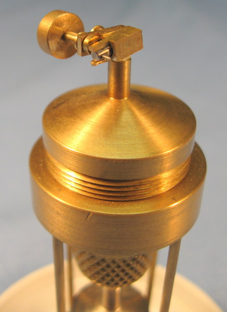
Pro Ball Turning Skillz
Ball turning attachments for lathes are common projects for the home shop machinist, but have you ever seen a professionally made turner? Here's what Dorian's looks like:
This turner goes up and over the top rather than side to side. Either method will work. Components consist of the arm that holds the tool, a level that delivers the up and over motion, the QCTP hub, and a worm and wheel gearbox with handwheel attached to move the cutting tool.
4/16/08
A DRO for the Lathe's Compound
I knocked together a quick DRO for my lathe yesterday:
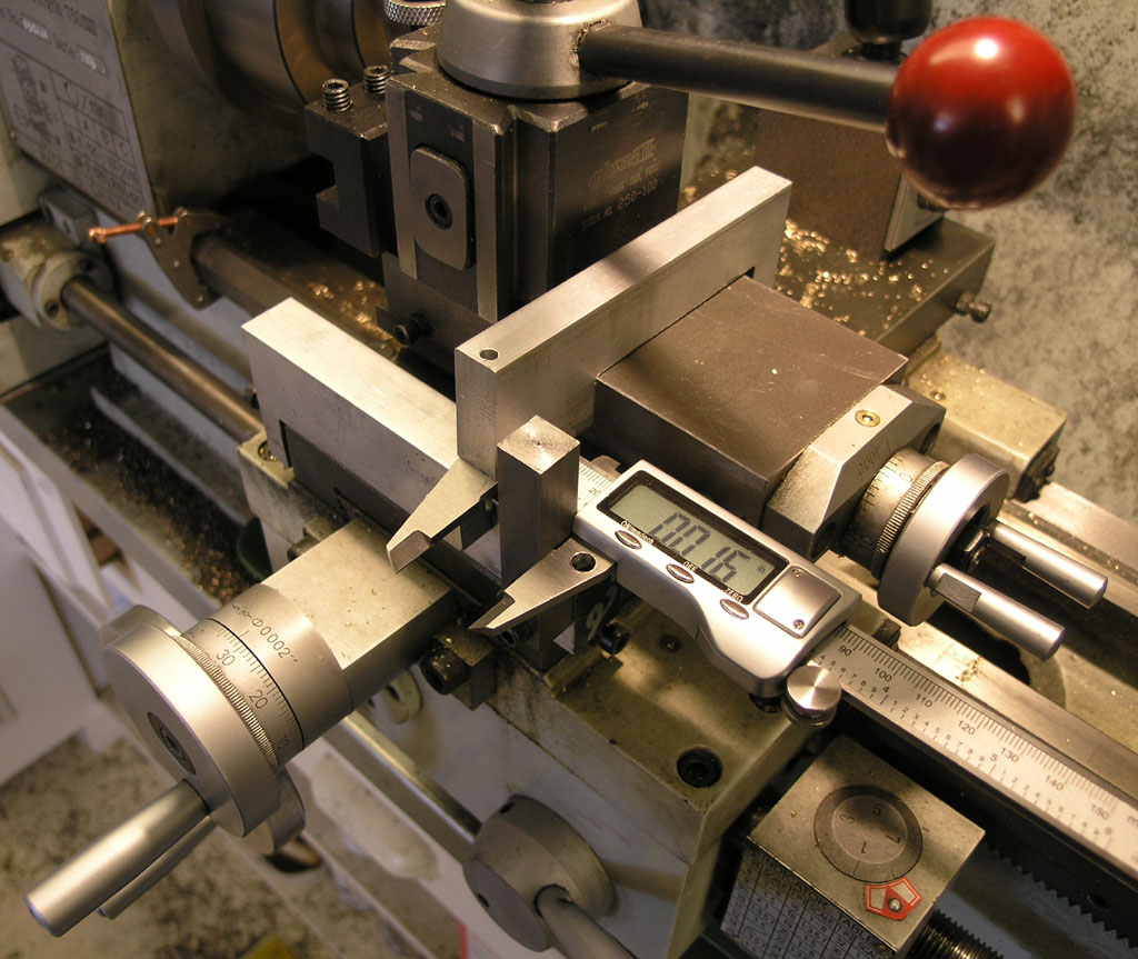
It's just a couple of aluminum blocks that clamp to the lathe. The calipers (I picked the ones whose feel I like the least. They were cheap from eBay!) are bolted to the bottom of the top block. The bottom block has a vertical bar to measure against. I found out the DRO is more accurate than the compound dial. Good to know!
The whole thing is easily removable too.
4/13/08
Good Stuff from Hilmar: Stuart Triple Expansion Project
Hilmar, over on HMEM, recently dragged out a set of castings for a Stuart Triple Expansion Marine Engine that had been stored for 37 years. And I thought I was a procrastinator!
This is quite an interesting project for three reasons. First, Hilmar is very good, and shows us some interesting techniques and tooling. More on that in a moment. Second, it's a gorgeous engine, intricate in every detail. Third, a lot of the parts are missing after all these years so Hilmar has to do even more machining than usual for that engine, and we get to see the work!
Go check out the thread, but meanwhile, here are some tidbits that caught my eye:

First, a $7.95 carbide blade purchased at Lowe's makes an awesome saw on the mill:
I can imagine it would be very handy, and you can't beat that price. Be a good excuse to make up an arbor...
The crank is also interesting. Starts out as a casting. Hilmar cleans up the square throws on the mill vise. That vise is exactly the right size to work. A grinding vise would also work.
Next, the journals have to be turned on the lathe. Note the little fixture that allows Hilmar to offset on the faceplate to place the throws on axis...
Second arrangement has the main crank axis on the lathe axis...
Now the T-bolt like gizmos or jacks. They support the "air" between the throws for greater rigidity...
4/12/08
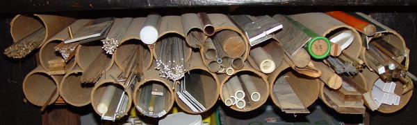
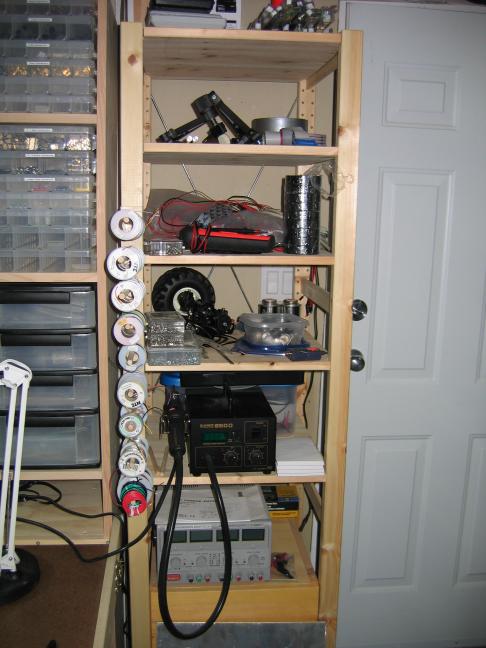
More Storage Ideas
Some prefer half-round gutter material, others like PVC pipe or cardboard shipping tubes:

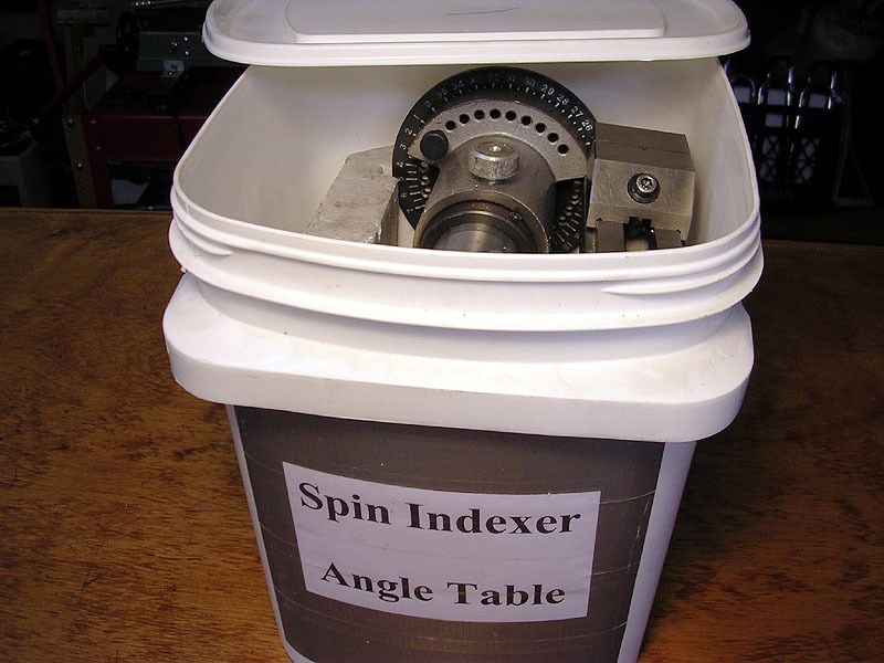
Even a kitty litter bucket can be pressed into service:
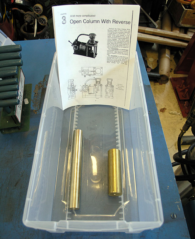
I latched onto a bunch of cheap storage bins and use them to keep all the pieces of a project-in-progress together along with a set of prints (I got this idea from Widgitmaster, natch!):
Dave Hyland's electronics workbench is pretty cool and very space efficient:
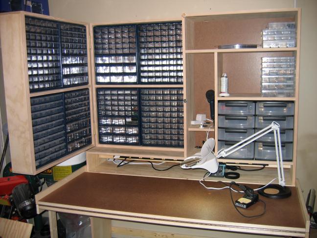
You could squirrel away a lot of tiny stuff here! Note the power strip in the cubby. Put your various goodies in there and leave them plugged in and ready for access. I would imagine that swinning cabinet makes sure not too much gets stacked on the left too. Very nifty!
Ikea makes a unit on wheels that is a perfect addition too...
4/10/08
Setting Up a Boring Head
There was a question about how to preset your boring head over on HSM I responded to today. I look at the boring head in the mill as completely analagous boring in the lathe. How would you preset things on the lathe? Most people wouldn't bother. To get to a proper dimension on the lathe, at least to a thousandth (tenths require a lot more fooling around), requires two things: you have to know where you are starting and you have to know how to turn the dials to take out what's left.
Think of a turning operation. To know where you are starting, you have two alternatives. Chuck up a piece of stock, take enough cut so you cut all the way around, and now stop and measure the diameter. Or, start with a piece of stock that you know is accurately round and of a known size. Dial that stock in on the chuck, touch off with the cutter, and you're ready to go! Touching off means to use a piece of paper while the spindle is moving and move the tool in until the paper is just getting grabbed. You're now typically within 0.001" of the surface with the cutter.
On a mill with a boring head, you get the same two choices. Start with a rough hole of some kind. Line up on it approximately or as precisely as you like. Adjust the boring head by eye to cut a bit out of the hole. Make a pass or two and then measure diameter. Now you know where you are. Or, you can do the other too. Line up carefully over a hole of known dimension that is also known to be round. Use a Blake Coaxial indicator or whatever your favorite method to get the spindle over the center. Now do the touch off paper trick with the boring head and you know where you are.
The other issue, knowing how to make the dials do what you need is important too. Does your boring head work by depth of cut or diameter on each marking? If I advance by 1 mark, did I make the hole 0.001" larger in diameter or 0.002"? Very important to know! Is the little dial accurate? Run some tests and get to know your boring head. My Criterion is a really beat up eBay special, but it is surprisingly accurate. So much so that I used it on my collet chuck project and got within about a thou of where I wanted to be without trying too hard.
Now when you need to cut to tenths, check back. I'm not there yet, so I can't help at the moment.
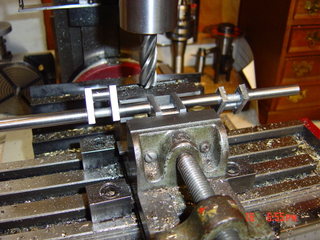
Collet Chuck Progress
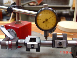
It's not done, but I've now gotten it dialed in to 0.00025", and I have one last step to finish. Here is how I measured the runout of the taper inside the chuck:
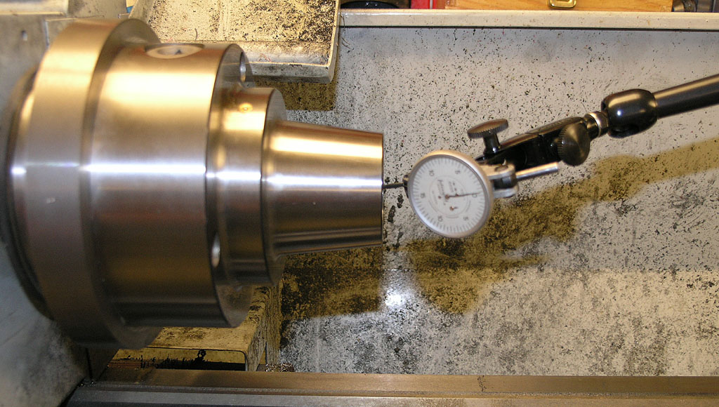
I should be able to finish this project soon!
4/6/08
Mounting a Collet Chuck on the Lathemaster 9x30
When I realized how small some of the parts were for the steam engine team build I'm doing, I decided it was finally time to mount the 5C collet chuck I've had sitting in its box for over a year. I started yesterday on the project and still have a ways to go. So far I have the mounting holes for the faux cam locks and a start on the spindle nosepiece bore:
There's been some interesting side trips involved too (aren't there always) such as making a set of M10 transfer screws and figuring out how to center that bore inside the triangle made up of the faux cam locks. Check out the pages I've started to document the process.
4/5/08
More HSM Carbide Sightings
The battle between HSS and Carbide Insert afficionados rages on. Not clear to me why there is a battle in the first place, but the HSS crowd continue to push what I view as a lot of myths about carbide:
Carbide Myths for HSM's
1. Small machines are not rigid enough for carbide.
2. Small machines don't go fast enough for carbide.
3. Small machines don't have the horsepower for carbide.
4. Carbide is too expensive for the HSM.
5. Carbide can't take fine cuts so it won't achieve the accuracy of HSS.
6. Cabide won't deliver as good a surface finish as HSS.
7. Carbide will heat up my workpiece, cause it to expand, and ruin the accuracy of my work.
8. You can't do interrupted cutting with carbide because the inserts are too delicate.
9. You can't do deep cuts with carbide on these small machines.
Every one of those is hokum in my experience. There is a reason the commercial world has all but abandoned HSS, and it isn't because they dont' care about all those "myths". It's because it's faster and easier. Recently, this discussion has popped up on the HSM board as well as the HMEM board. A couple of the fellas who are experienced with carbide posted great pictures that prove the point:
S_J_H takes a 0.125" cut in 6061. He regularly takes 0.100" cuts in leaded steel. He's doing this on a 9x20 lathe!

Evan is hard turning with a red hot carbide insert. Probably a hardened ballscrew or some such. This is on a lightweight Southbend lathe, very similar in rigidity to my Lathemaster 9x30.
Many from the HSS crowd will retreat to "I don't need to go that fast" or "HSS is better and cheaper, you just don't know how to grind the tools", but these HSM's are off doing awesome things with carbide on very lightweight lathes. No, Virginia, you don't have to have a Monarch or Hardinge lathe to use carbide!
|
Do you want to be a better CNC'er in 37 Seconds? Get Better Tool Life, Surface Finish, and Material Removal Rates Fast. It's that easy. You can install and get results now.

|
||||||||||||||||||
| ||||||||||||||||||