|
|
|
|
|
|
|
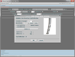
Do you want to be a better CNC'er in 37 Seconds? Get Better Tool Life, Surface Finish, and Material Removal Rates Fast. It's that easy. You can install and get results now. |
August Through September 2008 CNC Cookbook Blog Archive
9/30/08
Vertical Stop for Milling
Vise stops are really handy things for saving you work. Set the work up once against a stop and you can flip the part to take advantage of symmetry or stick a new part in against the stop and keep going without realigning the mill. I made one that I use constantly, and I use small Kant-Twist clamps as stops as well. But I never thought of creating a vertical stop until I saw a thread on uses for 1-2-3 blocks on PM.
This fellow needed to run a corner rounding mill over a bunch of parts with different thicknesses. Rather than painfully set up the depth of cut for each thickness, he came up with the idea of using 1-2-3 blocks and a cross bar to create a vertical stop. He'd use one hand to raise the workpiece against the crossbar while making sure the crossbar was firmly down on the 1-2-3 blocks, and then use the other hand to tighten the vise. Here's his sketch of the setup:
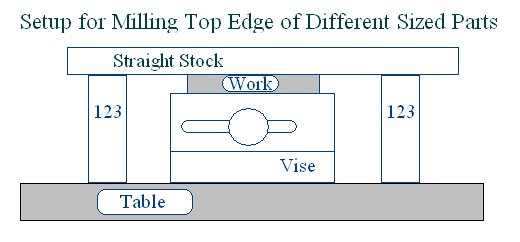
Clever!
9/27/08
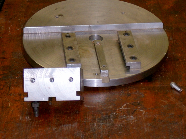
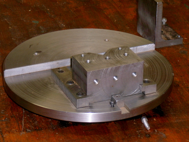
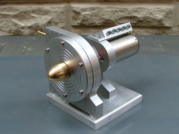
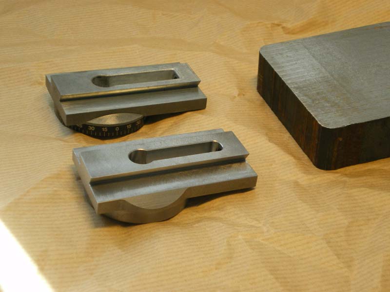
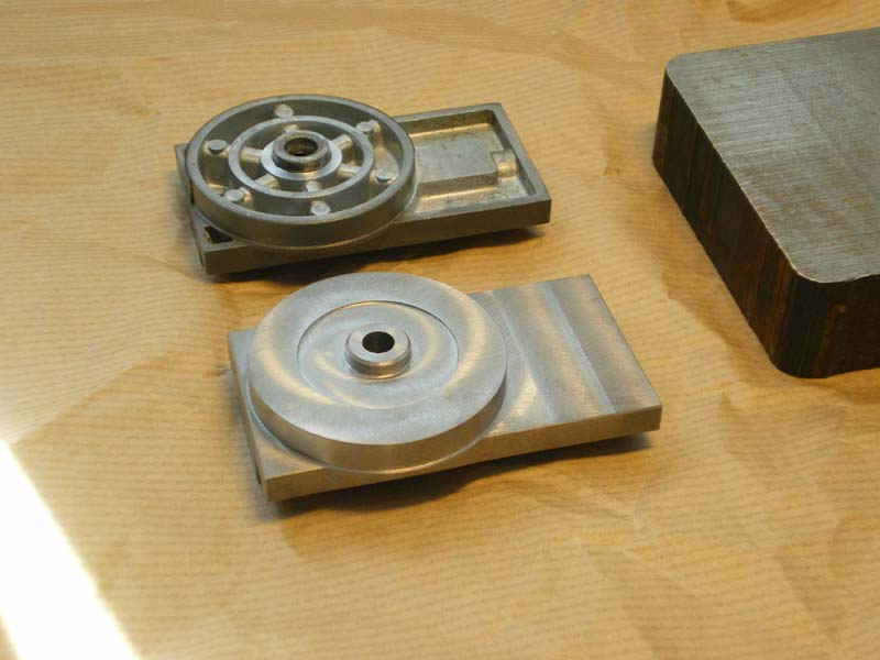
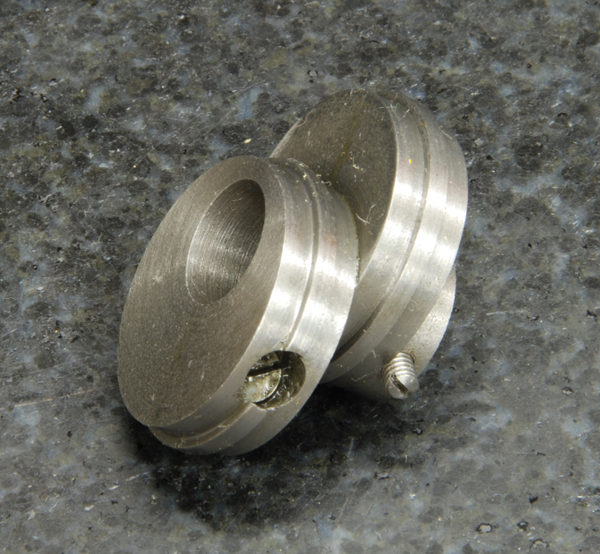
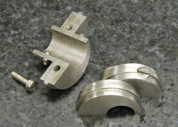
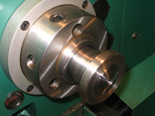
Faceplates for Eccentric Turning
Over the years, some people have built special fixtures to make eccentric turning easier. It's common when building engines and other projects to have to do eccentric turning to create cams or crankshaft offsets. Here is one such faceplate that accomodates either a flat tooling surface or a v-block to hold the workpiece at various offsets from center::
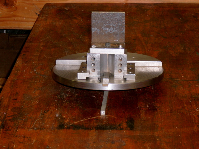
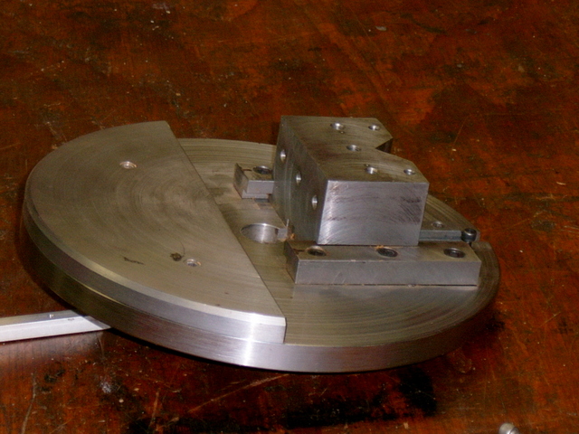
See my page on Eccentric Turning for more on these sorts of fixtures and practices.
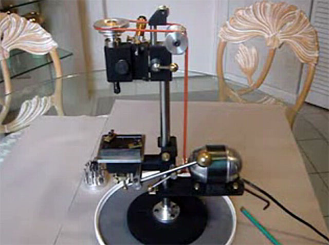
An Automatic Bar Feeder for a 4x6 Bandsaw
I'm fascinated by all things "automatic". I don't know why, as I'm not running a manufacturing facility, but somehow these things just attract me. Here is a marvelous air-powered bar feeder for a small bandsaw that I found on the Chaski Boards:
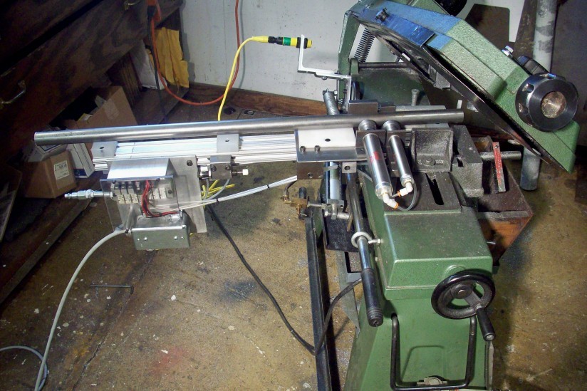
The overall feeder
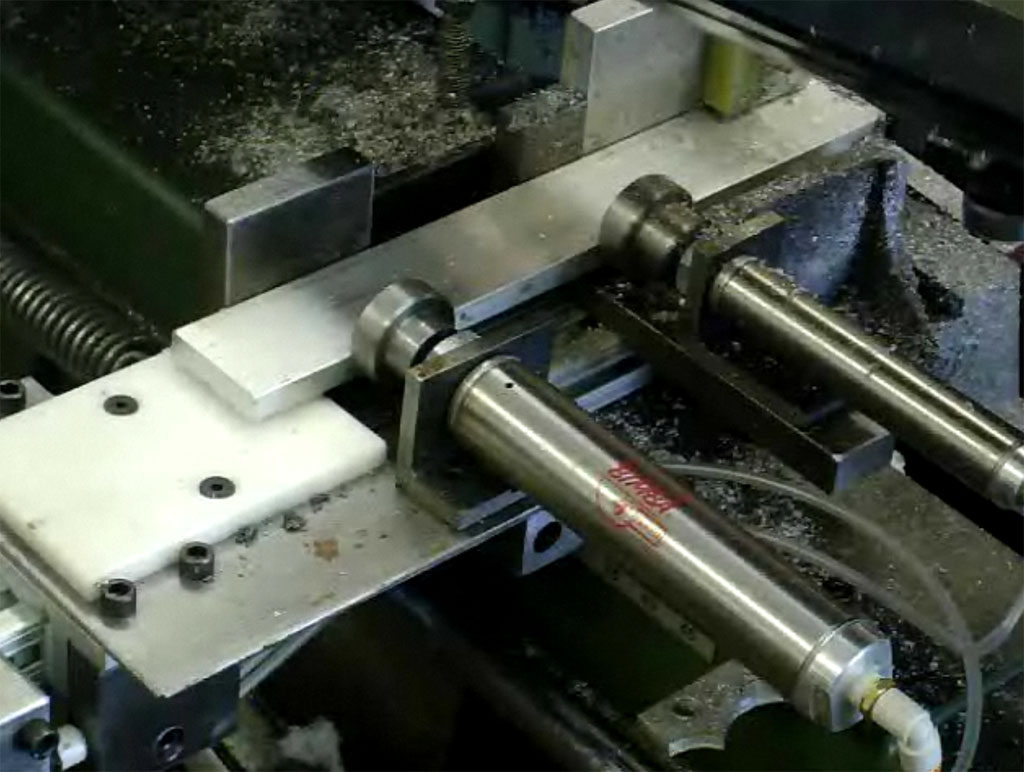
Feeder clamps. Cylinder on right is fixed. The one on left is on a sliding bed. To feed, release the right, clamp the left, and slide forward. Clamp the right, release the left, and slide back. That's one cycle. Here is a video of the feed cycle:
The air cylinders are actuated by SMC air valves, and the overall automation is controlled by an Allen-Bradley Micrologix 1000 PLC.
Is that cool, or what?
A Tribute to John Bogstandard
I've put together a bit of a tribute to the model steam turbine work of Bogstandard, who has contributed a number of articles on the HMEM boards. John is another of those rare guys who not only does fabulous work, but shares his methods in a way that makes it possible for all to learn. One of the most fascinating areas John worked in was that of model steam turbines. I'm quite sure I hadn't seen such a thing before coming across Bog's engines, but they sure look fun:
Visit the Model Steam Turbine Page for More Info...
At some point I shall surely have to try my hand at making one of these beauties!
9/23/08
Liquid Tite Conduit
The conduit used here is called "Liquid Tite" I believe. Makes for a clean installation!
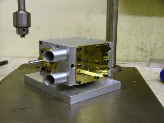
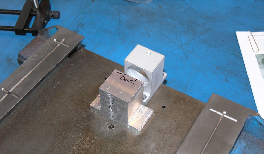
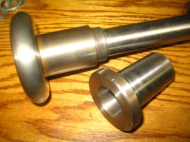
Cruel Teaser Sketch
Just the one "spy" photo of a little something I'm designing:
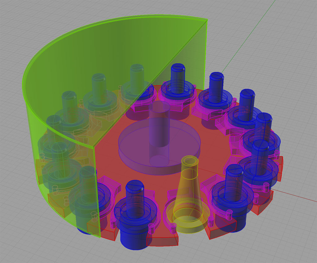
Curious how there are two different kinds of tool holders, eh?
State of the IH CNC Mill Project: One Shot Works for X-Y and X and Y are "On the Bracket"l
There's been quite a lot of progress I've been slow to report on, so this is a catchup post in pictures in no particular order:
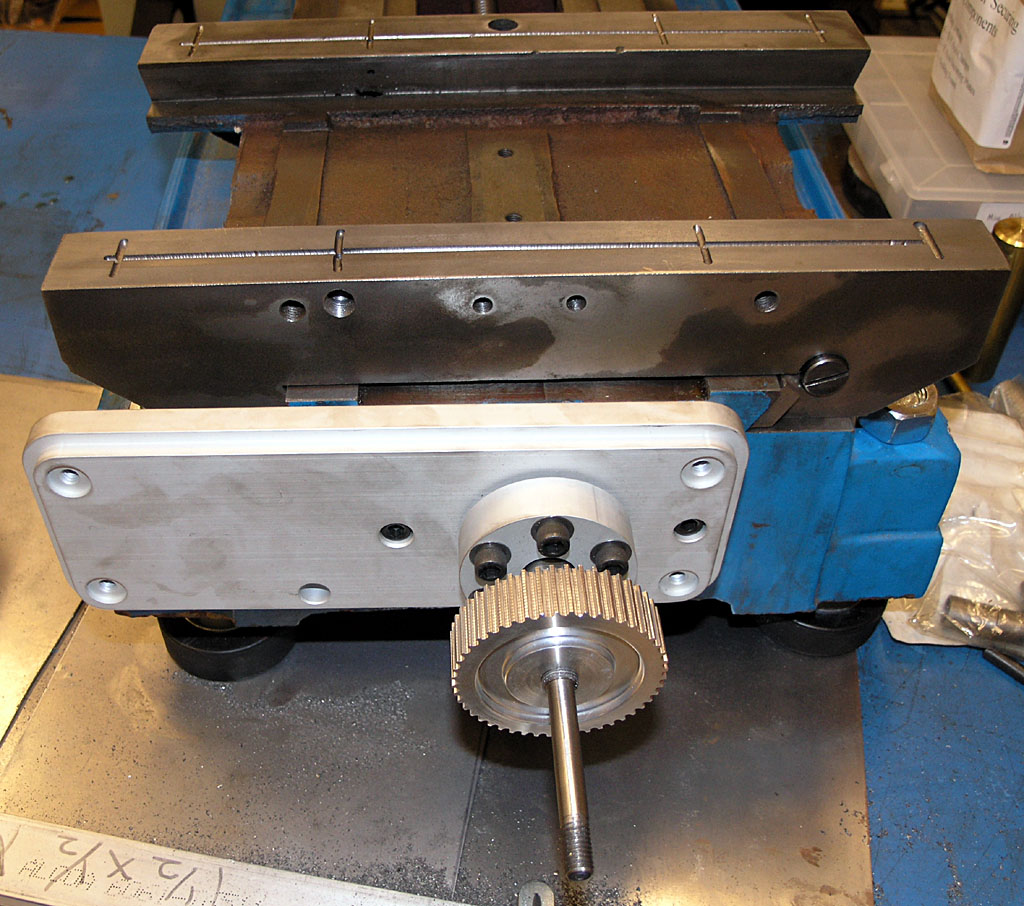
X-Axis is assembled and "on-bracket"...
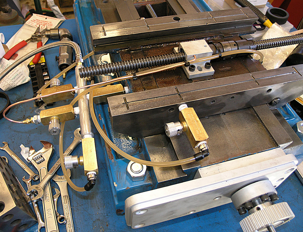
One shot oiler for the X and Y axes is now up and running well. Between the way lapping and the one shot, I can tight the gibs as tightly as they can go with a screwdrivers and the axes still move like velvety smooth butter...
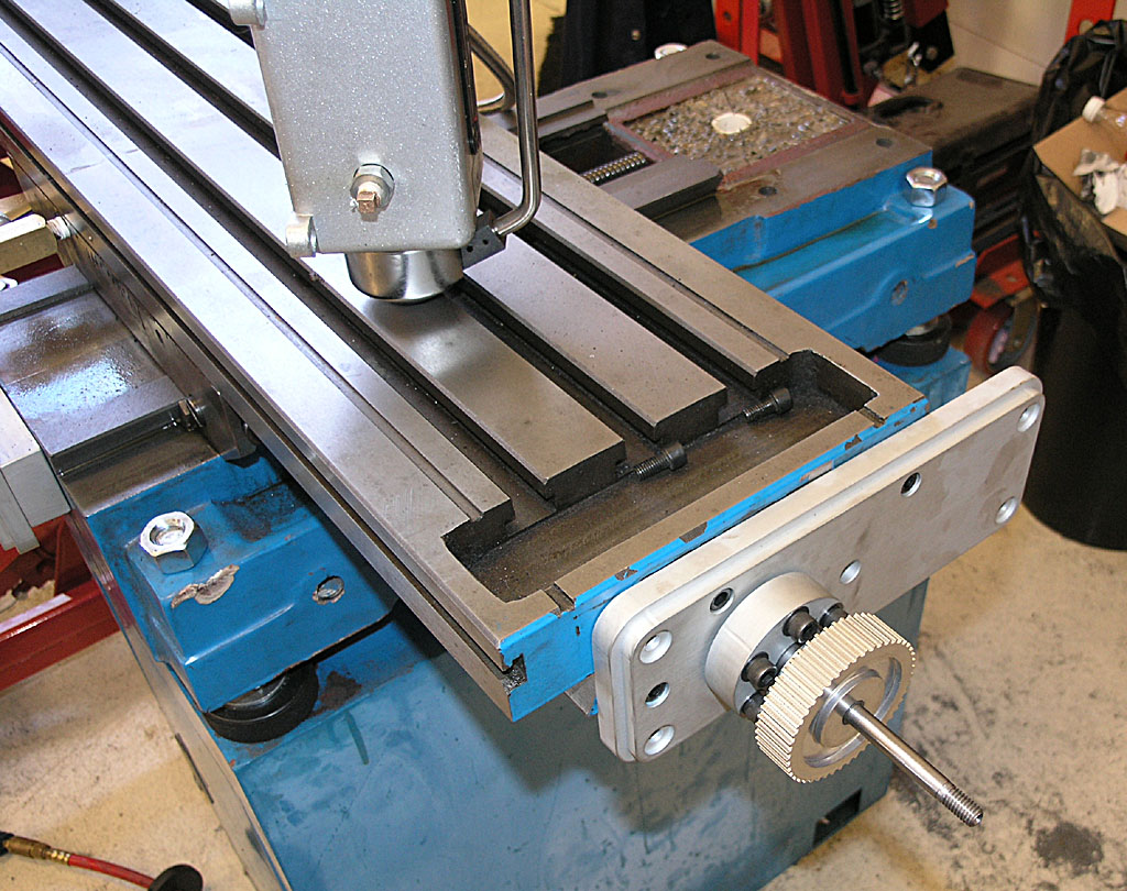
X-Axis is "On-Bracket"...
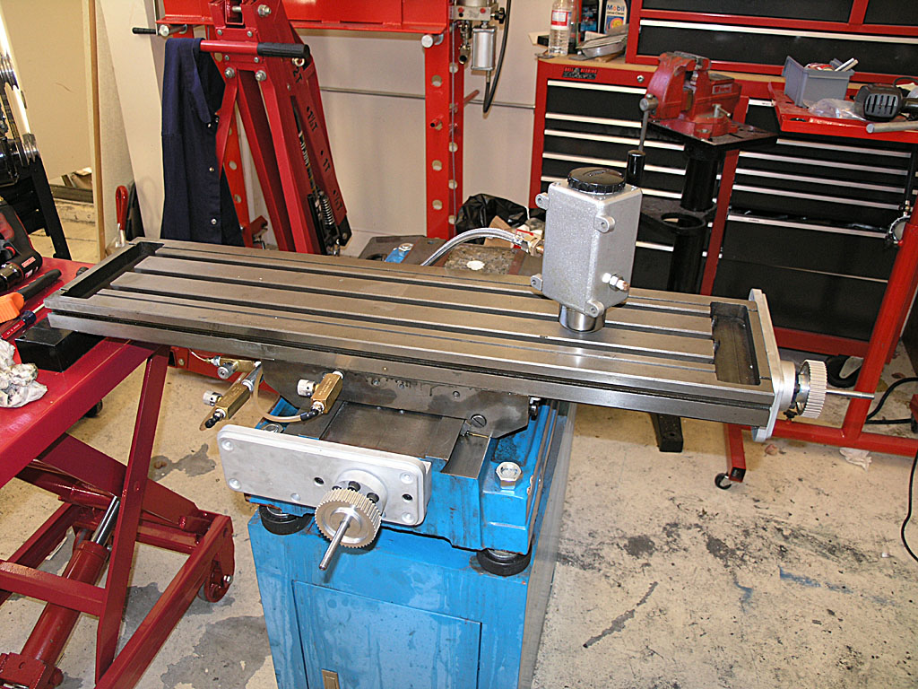
Here's Where We Stand: One Shot Works Great on X-Y. Ballscrews and Brackets are Mounted on X-Y
Next Step: Mount the Column. I made a change from IH's directions. If you mount the column and then try to install the ballscrew, it is hard to access the top of the column without a ladder unless your machine is on the floor. So I mounted everything temporarily and then disassembled it. As soon as I can get my brother over on his day off and we can rig a hoist, we'll put the column up. The holes for the mounting the ballscrew and servo are all drilled and tapped, so it should be fast. After that, I need to:
- Plumb the Z-axis oiling--note that there is a plugged outlet on the other side of the one shot pump for that
- Make a mounting plate for the One Shot Pump that goes in the opening for the hand crank on the Z-axis. It'll do double duty blocking off that opening and mounting the pump.
- Mount the servo motors. My NEMA34 frame motors fit the IH brackets just fine (yay!). I need to look at what's required to mount the timing pulleys to these servos, however. I also need to get a set of belts from IH.
- Mount the optical limit switches on all 3 axes.
- At this point I'll be mechanically complete on the conversion and it'll be time to start looking into the electronics.
Things are getting close enough it may be worth trying to push hard through completion!
9/14/08
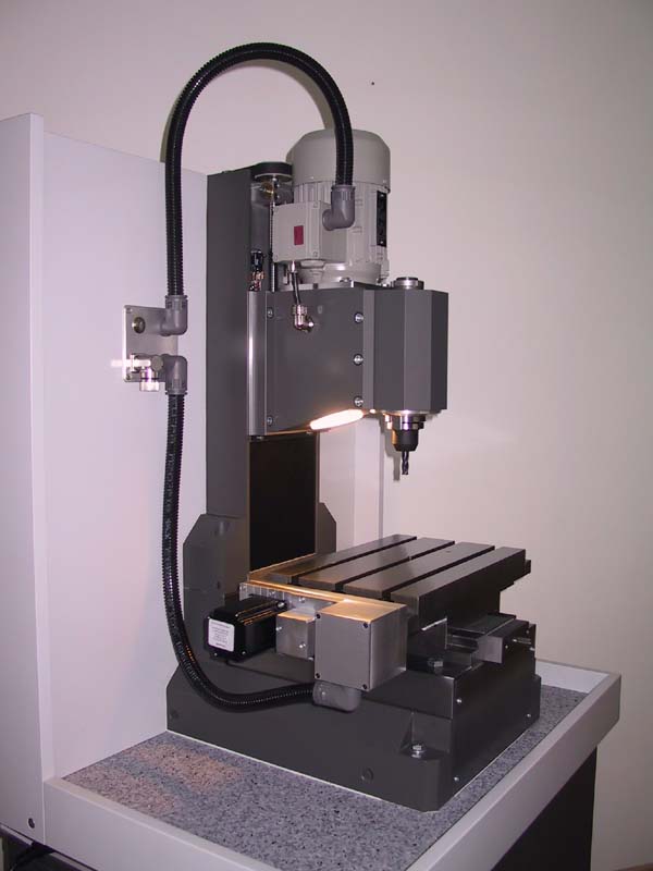
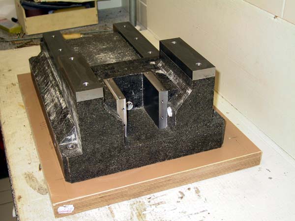
German Epoxy Granite Milling Machine
Here's an awesome project I recently heard about on CNCZone:
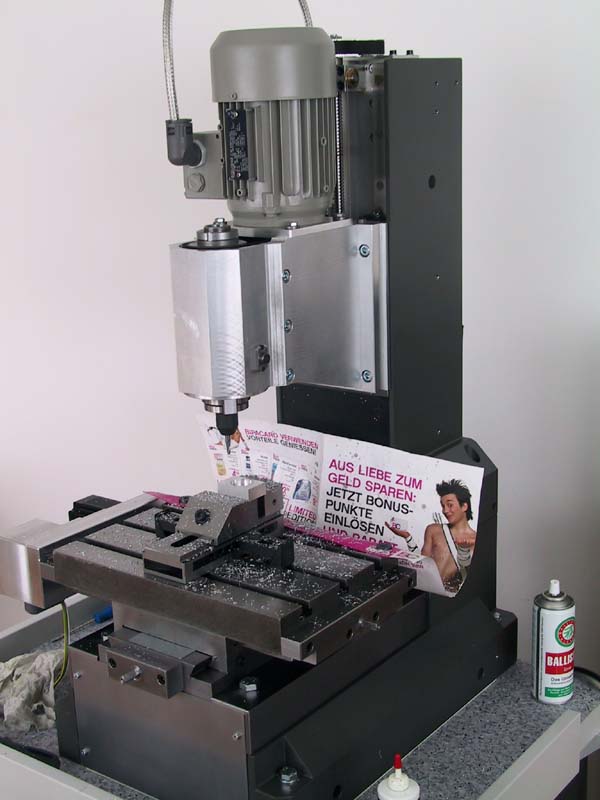
That machine is solid!
A few details I gleaned from one of the articles on the German site (you have to register!):
The epoxy granite mixture being used is 30% granite gravel, 30% joint sand, 30% fine quartz sand, and 10% R L & G epoxy resin. Based on my research, that should make for a fine epoxy granite base. And here are some interesting build pix:
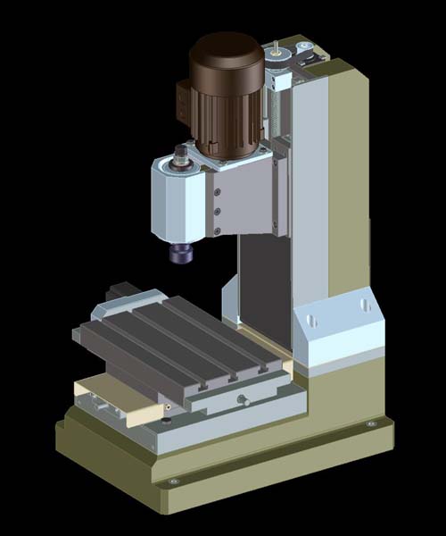
Original Drawing...
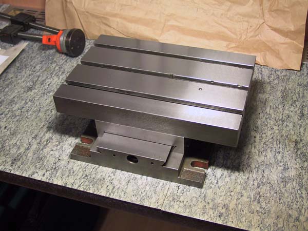
Table/Saddle Will Be Incorporated into the E/G Matrix...
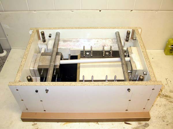
Mold for the base. This base will be case upside down. Note the screws sticking up from the metal parts--that's how they're anchored into the epoxy matrix...
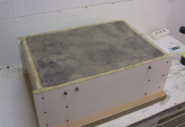
The Epoxy Granite Has Been Poured Into the Mold...
Looks Promising! Wondered how he would get it to release. I like the use of melamine. Probably a release agent would make the mold reusable...
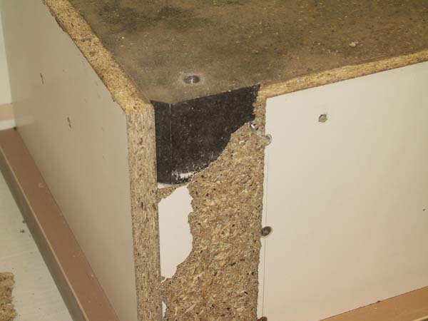
Front of the base. Note the precision steel pieces cast in place...
And the rear...
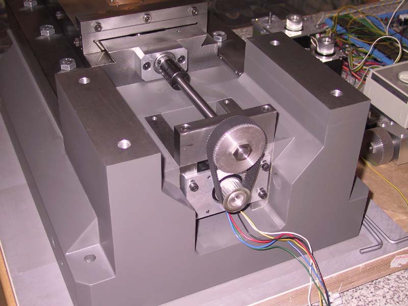
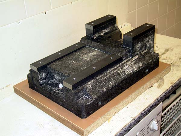
Painted and assembly underway. The Y-Axis mechanism is under the column. That much solid epoxy granite has got to make for a more rigid machine than the normal hollow cast iron!
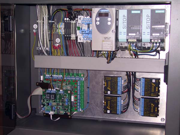
Extremely clean electronics chassis...
Note the built in light! Looks like that will be the enclosure. Another nice piece of work...
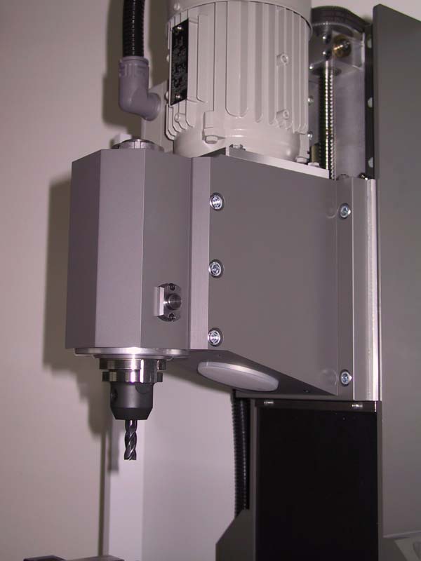
Not sure of the taper. The text mentions SK30. That's a release button on the side, so there must be a compressed air drawbar with bellville's or some such...
Sample part: a lathe slide for an Emco 5. The original he says was warped. The new one is cast iron...
What a spectacular project!
9/13/08
Widgitmaster Mini-Routers Are For Superheroes Too!
On CNCZone is a fellow making superhero costumes with the aid of his Widgitmaster mini-router, and boy are they cool! Check out this resin part for an Ironman costume:
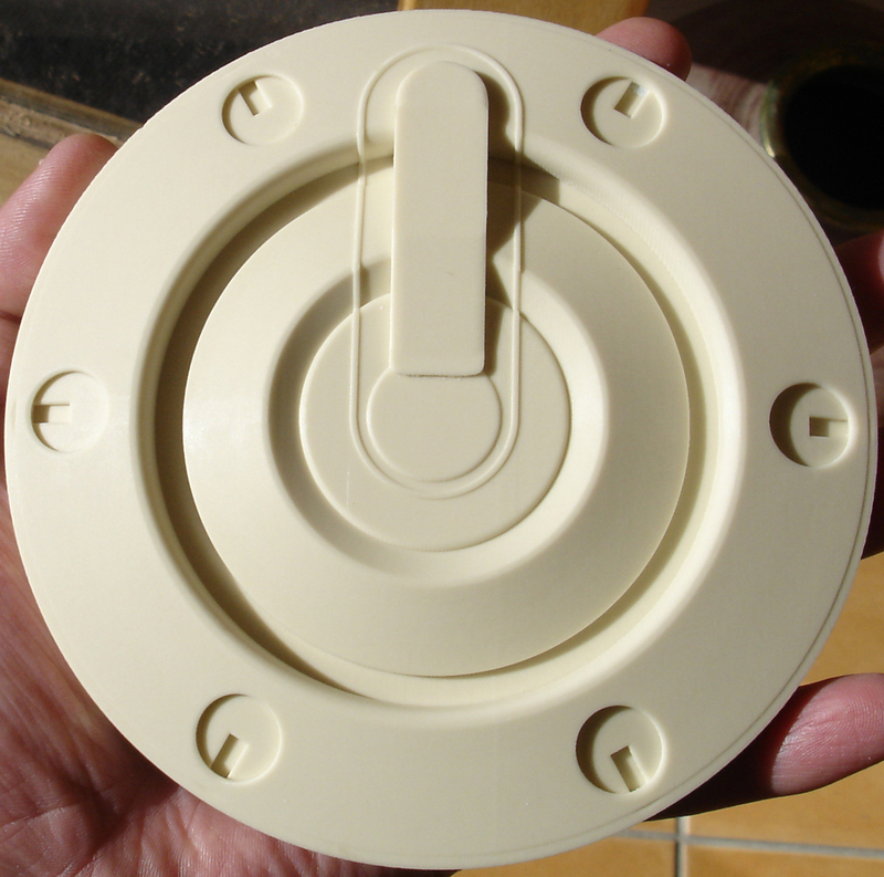
That fabulous finish came about in 4 passes: 1/8" rough cut bit, 1/8" parallel finish 10% step, 1/8" parallel finish 5% step but with the part turned 90 degrees, and 1/32" finish with 10% stepover. Apparently it took 6 hours, but dang, what a finish!
Check this talented Australian's site for more info on costume making.
9/10/08
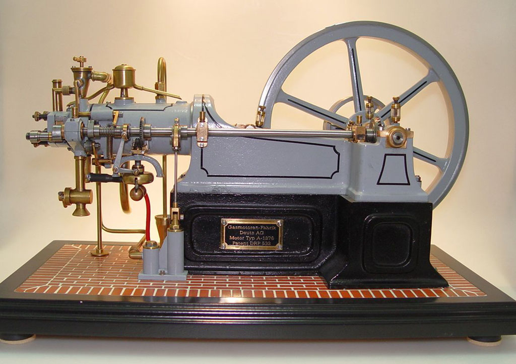
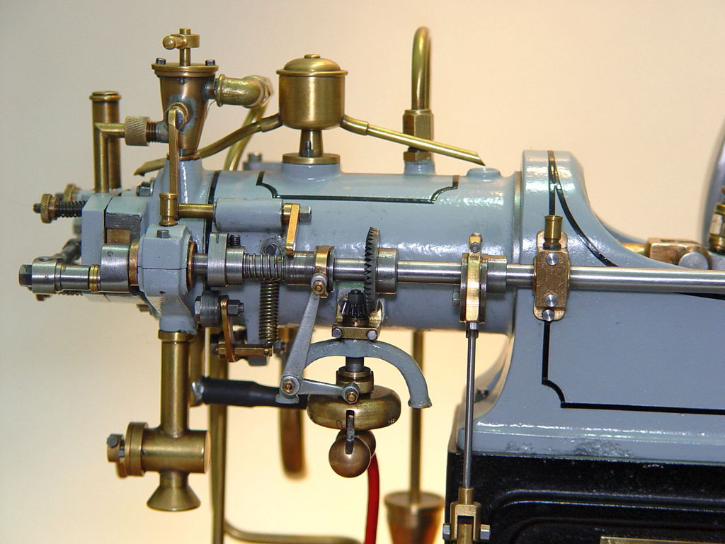
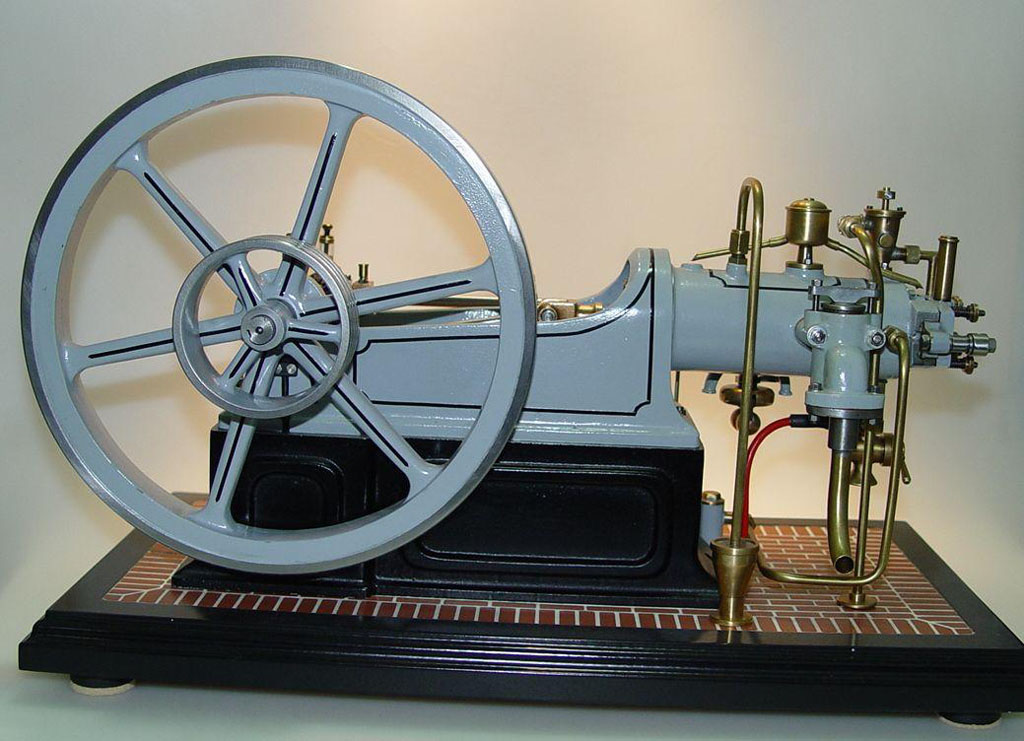
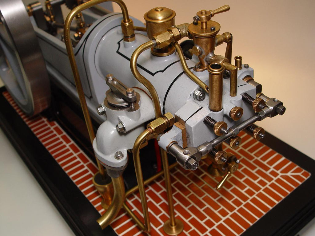
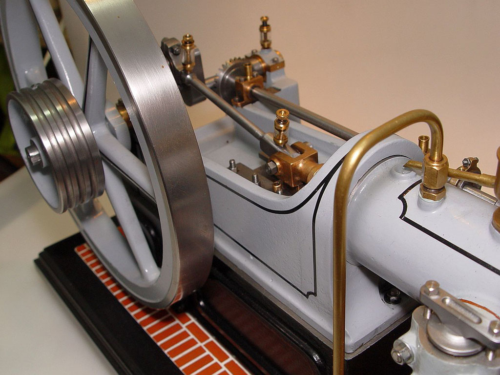
Gorgeous German Four Stroke Model Engine
I found this beauty by way of the excellent Chaski site. This engine is powered by butane and includes such nifty features as a centrifugal speed governor and a water pump to circulate cooling water.
Rigid Tapping Spindle Speed Accuracy
The question of rigid tapping comes up often in CNC. Can I chuck up a tap in a rigid holder and tap holes successfully? In theory, if we can move the tap vertically in a manner synchronized with the rotation of the spindle, the answer is "yes". But how accurately must we control the spindle speed to accomplish this task? Let's do some math:
10-24 Rigid Tapping
Assume we have a 10-24 tap. It has 24 TPI, and so the width of the thread during a single revolution is 0.0417". So, for each spindle rotation we need to move the tap down into the hole 0.0417". If we're running 800 rpm, that means a Z speed of 33 1/3 inches per minute. Now let's say we have an error in our spindle speed, and it is not precisely synchronized with the Z motion. For example, let's say the spindle is off by 5% (too slow or too fast, doesn't matter). Further, let's say we're going to tap 1/2" deep holes. How far off is the tap by the time we get to the bottom of the hole?
I make the error by the bottom of the hole as (5% * 0.0417") * (0.500" / 0.0417") = 0.025". 25 thou is a pretty big error in just 1/2"! Another way to look at it is that 25 thousandths is 60% of the 41.7 thousandths thread width. Things are going to be pretty bunged up in the bottom of that hole!
Let's suppose we want to be accurate to 0.001", a common consideration for back of the envelope studies. In that case, we need the spindle to track within 0.2% of what we expect. Note that this means the spindle must not only hold its speed constant to that degree, but it must also be possible for our CNC controller to accurately tell it what rpm to run at within that degree of accuracy. Many VFD's have a range of error just from taking in the analog signal that controls their speed. For example, here is a fancy Yaskawa Vector Drive that says analog inputs are only accurate to 0.5% with analog input--not enough for our task. In addition to having an encoder on the spindle, we also have to interface a digital input to our VFD to ensure accuracy on that side. This is getting complicated!
Let's try another example:
5/16" 18 TPI Rigid Tapping
Bigger bolt, so I'm assuming we want to thread 1". With a spindle accuracy of 5%, I get a total error of 0.050", which is again way too much! If I can get control to 0.5", my total error falls to 0.005". This is an error of 9% by the time we get to the last thread. That might be tolerable, just.
What to do? Compression/Expansion (aka "Floating") Tap Holders
As you can see, the requirements on the machine to do rigid tapping are fairly extreme. This is why most of the time an encoder on the spindle is required and the CNC controller normally talks to it. What to do if you're running Mach 3 or some other controller that doesn't even support rigid tapping?
Have you ever done any power tapping? This is where you use a drill press or mill with a quill, you chuck up the tap, you turn on the spindle, and you gently guide the tap to the hole. Once in the hole, the tap drags itself down as it cuts. Works great. We can employ this same principle fairly well with a compression/expansion tap holder. This is a holder that allows a little play along the axis. You can see from the numbers I've provided that a tremendous amount of play is not required. A couple tenths of an inch would be great, especially if we can set up the tap holder so the play is in either direction. We then program the CNC to the best of our abilities as though we were rigid tapping and we let the tap holder absorb and errors of synchronization between the spindle's exact rotation and the motion feeding the tap.
This method works great, is fairly inexpensive (try Maritool for tap holders, for example), and let's us tap without a cumbersome tapping head on the CNC machine or an expensive controller and spindle capable of true rigid tapping. Note that these holders are also referred to as "Floating" tap holders.
Mounting Ballscrews On Small Lathes
It's often a problem to mount a ballscrew on the cross slide of a small lathe. There's just not much room under there, particularly if you're tyring to fit the ballnut where the original ACME nut went under the slide. Here is another approach if you have a ballscrew with enough travel:
Ballscrew goes under, ballnut is on the left outside the slide itself...
In this design the ballnut is out from under the slide and sticking out where the handwheels would be. The main disadvantage will be the much longer screw needed as all the travel has to be available outside the slide.
9/02/08
Sears Labor Day Sale Yields CNC Cabinet For the Mill
I've ordered a Sears Gladiator Modular GearBox:
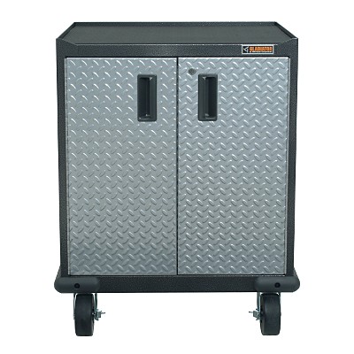
Inside is a cabinet with 1 shelf on slides. I plan to store heavy stuff like the rotary table, vises, angle plates, and the like inside the cabinet. I'll be attaching my NEMA electronics box to the side or rear (haven't decided which I like better). The PC and all the mill's electronics will go inside that NEMA box. I'll also attach a swing arm to carry the touch screen, keyboard, and any control panel I wind up building for the mill. I have a spot in the shop right adjacent to where the mill sits that is perfect for this little rolling cabinet. Should make for a very neat and professional installation. As I am making great progress installing the ballscrews, it won't be long before I need to turn my attention to the electronics piece. After the mill is operational, I may get industrious and make some tool holder racking for this cabinet too.
8/31/08
Drill Press Page Updates: Table Lift, Table Indexer, and Sensitive Drill Presses
I keep a page of drill press-related projects. The homely drill press is often the first metal cutting machine people get, and while they're not milling machines, they can be extremely useful even once you have access to a mill. It's worth adding on a few gizmos to make your drill press even more productive. Here are some highlights of the new photos:
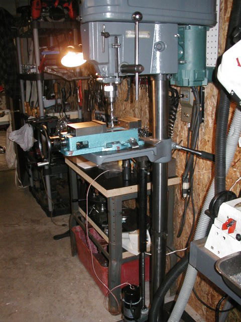
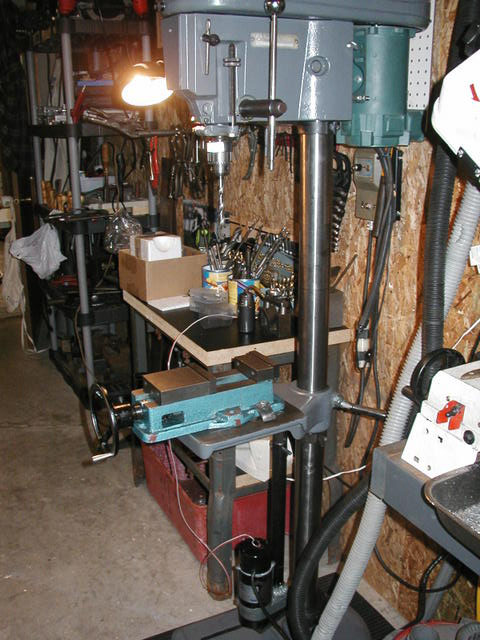
Power lift on the table. Here it is cranked way up and then all the way down. Nice to have a milling vise on your DP!
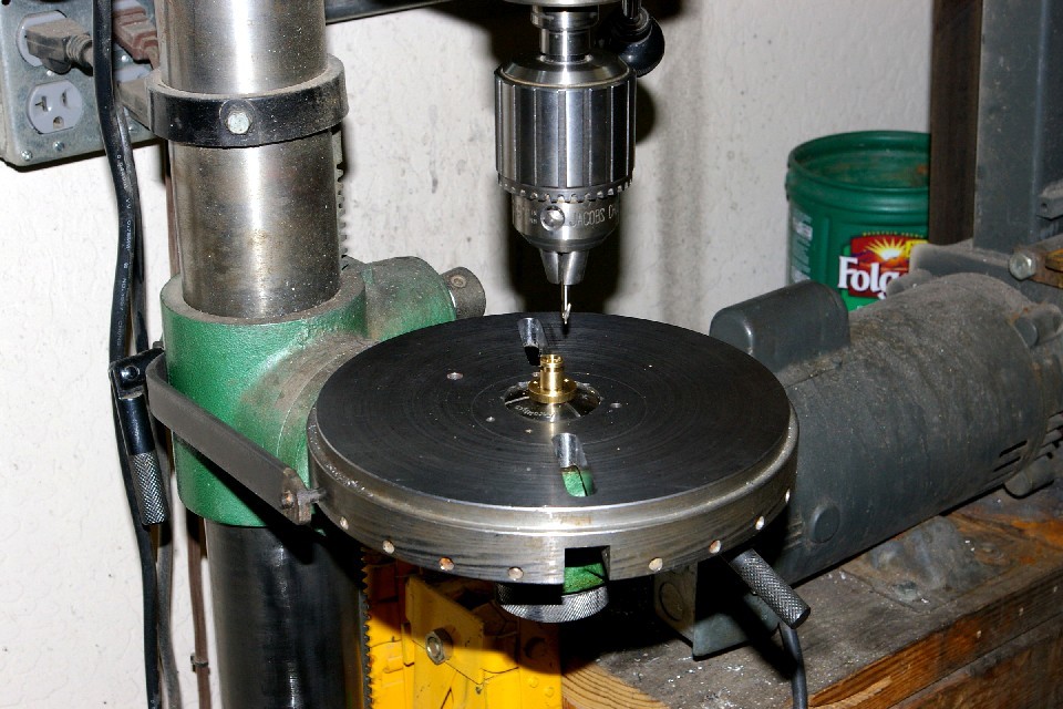
Rotary indexer sits in place of the normal table. The indexing arm is attached to the column. The center holds a 5C collet.
Nice photo series of a shopmade sensitive drill press...
8/24/08
Meanwhile, Considerable Progress on the Mill CNC Conversion Today
Finished the Y-Axis Ballnut Mount...
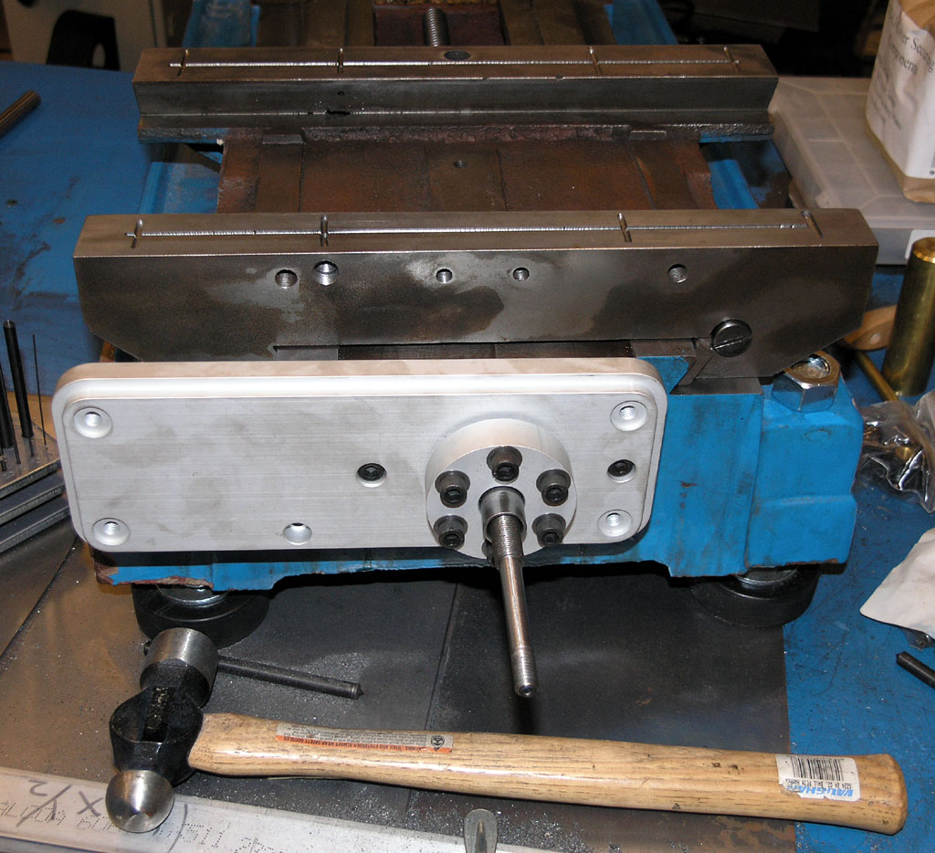
Which Enabled Me to Get Started Installing the Kit. At Last!
Pretty Nifty Looking, Eh?
Check Valves, Gate Valves, Regulators and Other Useful Model Steam Fittings
I notice that the Golden Gate Live Steamers web site has some extremely useful information on their Tips and Techniques section. Especially good is the section on check valve design.
8/17/08
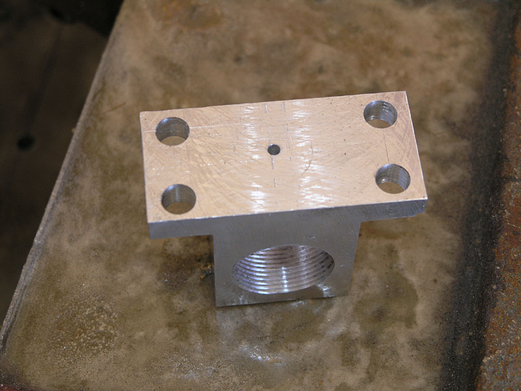
Building a New Y-Ballnut Mount
Spent a few hours in the shop today and made rapid progress in a short time on this Y-Ballnut Mount:
The factory mount hangs off the edge and you lose 2 bolts. My new mount has all 4 bolts to hold down the ballnut...
Just finished threading it and it fits!
Very Cool Model Boiler
Came across this very cool little boiler on HMEM:

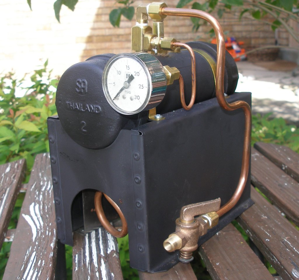
The rivets really make the enclosure. It would not be that hard to machine the end caps so they're less obviously pipe fittings and to arrange packing to further mask the origins. Add some fittings that are a little more to scale and it would be really excellent. It's really cool as it is though.
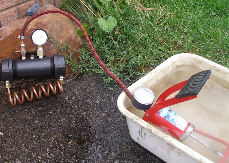
Pressure testing with water. You can see the water tube here very clearly. Copper, so it transfers heat well...
Check the video of the test. Builds steam fast!
8/12/08
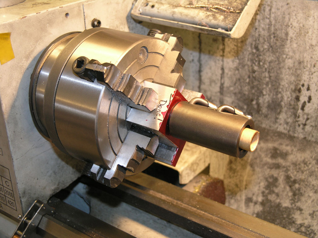
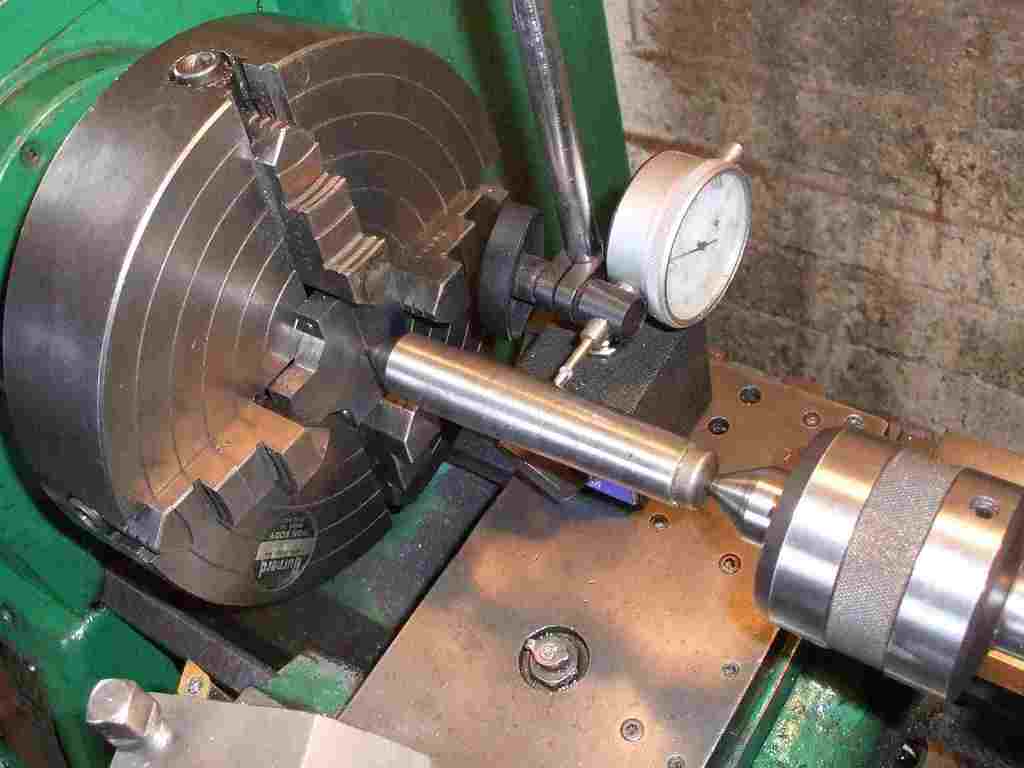
4-Jaw Dial In Setup
While researching eccentric turning I came across this nice shot of dialing in an irregular part (or a feature of a part) on a 4-jaw:
New Cookbook Article: Turning Eccentrics on the Lathe
A compendium of techniques I've researched to do eccentric turnings like this one:
3 different axes to turn for this double eccentric from a triple expansion steam engine. See my Cookbook page for some ideas on how to go about doing this sort of thing...
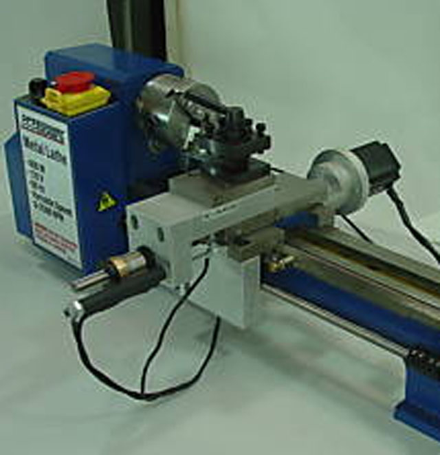
Prototrak 1630 CNC Toolroom Lathe
I like looking at CNC toolroom lathes like this Prototrak or the Haas TL-1. Some day soon I plan to buy a bigger lathe than my Lathemaster 9x30 with an eye torwards converting it to something like one of these machines.
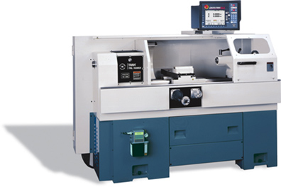
I'm envisioning that the window can be made to track the cross slide as it moves so as to deflect chips, and then unlocked to provide full access when setting up a job. The challenging thing about a job like this is virtually the only keepers are going to be the ways (potentially including the cross slide), the spindle, and the tailstock. The quick change gearbox and the various leadscrews will be junked and replaced with ballscrews and servos.
5C Lathe Hijinks: Closers and Boring Bar Holders
I love my 5C Collet Chuck, so I always perk up when I see 5C goings ons. Here are a couple items of interest.
First up, a nicely made 5C closer:
#5 Morse Taper on the Nosepiece so it lines up properly in the lathe. My lathe only has a #3 MT, so a closer like this wouldn't work. I'd have to mount the nosepiece ala my collet chuck on a backplate.
Here we see the nosepiece installed. Note the camlock D1-4 on this lathe.

The closer end of the drawbar...
5C QCTP Holder: I thought this was a great idea. This will be a good one when I get the CNC lathe going to turn the taper inside. I'll set it up to use the tightener from one of my collet blocks. The builder of this device says it holds the boring bar a lot more rigidly than the normal setscrew holder.
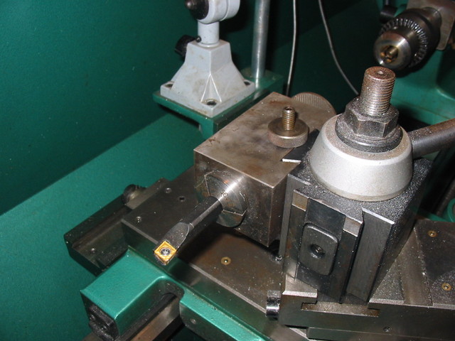
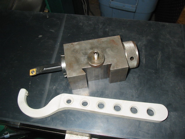
I like the nice tightening spanner too so you can get things good and solid.
8/2/08
Got a Couple Hours Shop Time in Today to Keep Going on My CNC Mill Conversion
Here are some photos of the Z-axis ballnut bracket, and some one shot oiler work:
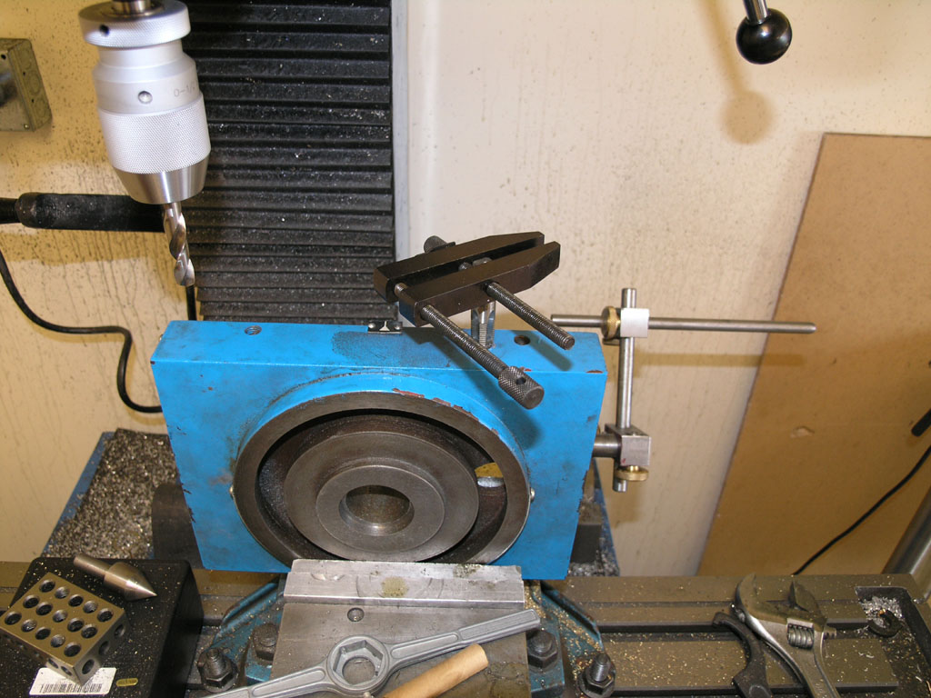
Tapping Z-axis...

Cross drilling...
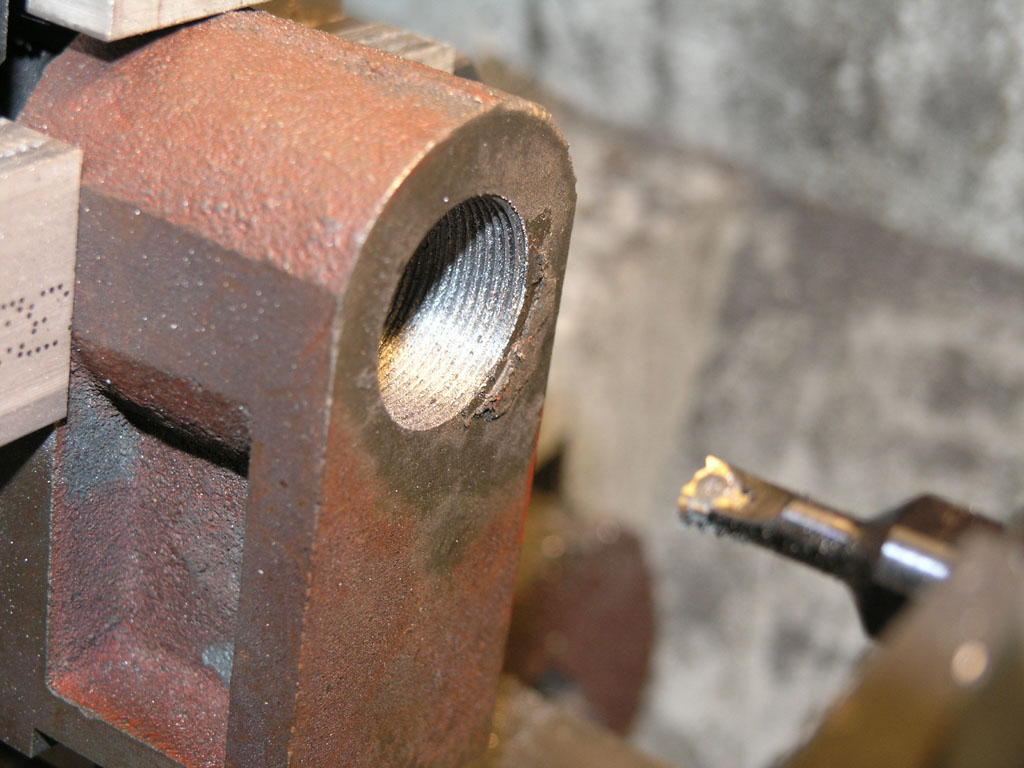
Here's what it looked like after a couple of passes with my Carmex indexable threading tool. I cut each pass less deep. Due to the triangular cross section, each pass is removing more material if you cut the same depth. As I recall, I used 0.010, 0.006, 0.004, and 0.004 to remove the total 0.024" required for the thread...
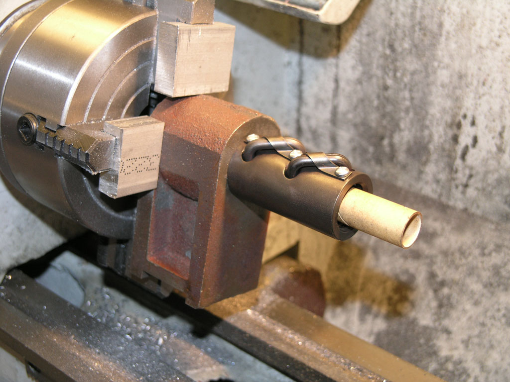
Fits like a glove! Note: that cardboard tube keeps the ball bearings from falling out. That would be really bad if it happened!
I've now drilled and plumbed the oil passages on Y and Z. I need to do the passages on X, and I need to modify the various ballnut brackets on all three axes to deliver some oil to the ballscrews/nuts. After that, my "off the map" mods are done (sans bracketing and plumbing the one shot, but I plan to do that on the assembled mill) and I need to start the CNC kit assembly per IH Hobbies instructions. I've been reading over those to make sure I'm real familiar before I start.
|
Do you want to be a better CNC'er in 37 Seconds? Get Better Tool Life, Surface Finish, and Material Removal Rates Fast. It's that easy. You can install and get results now.

|
||||||||||||||||||
| ||||||||||||||||||