|
|
|
|
|
|
|
Do you want to be a better CNC'er in 37 Seconds? Get Better Tool Life, Surface Finish, and Material Removal Rates Fast. It's that easy. You can install and get results now. |
February Through March 2008 CNC Cookbook Blog Archive
3/18/08
A Trio of Lathe Productivity Aids
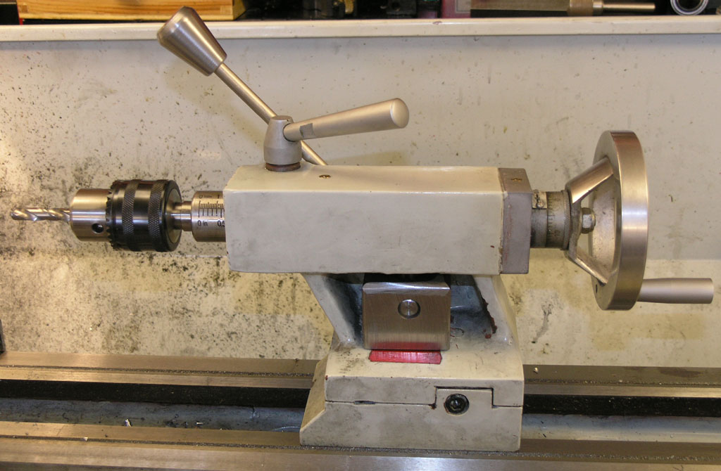
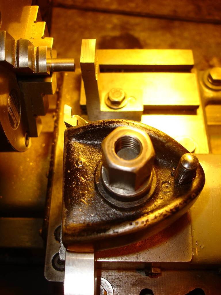
First, I built a camlock for my tailstock. Man has that ever been a joy!
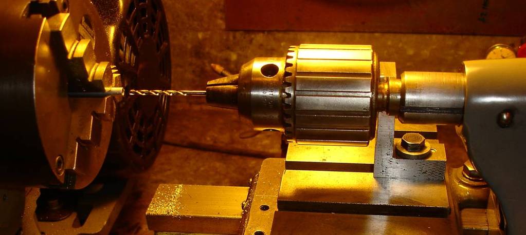
Second, I got a nice keyless chuck on an MT2 taper from Lathemaster.com. They're inexpensive and well made, a rare combination in this business.
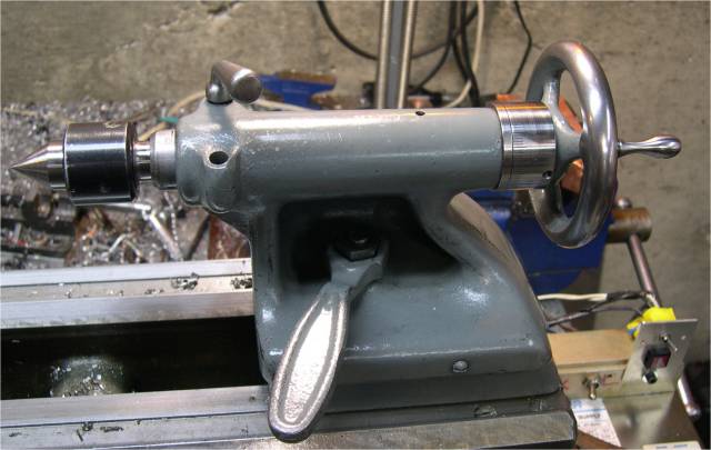
With these two innovations my tailstock is now totally wrenchless other than setover for tapers and so much the better for it:
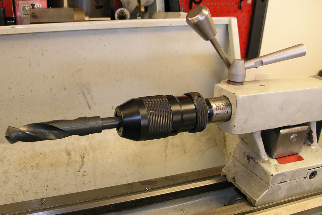
Look Ma, no wrenches!
Third, I've taken to using a small Kant-Twist clamp as a carriage stop. It fits perfectly and is very convenient:
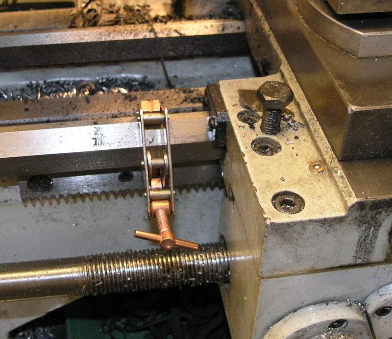
A handy carriage stop...
3/18/08
Team Build: Elmer Verburg's Reversible Open Column Steam Engine
I'm joining a team build for this engine that was organized over on the HMEM board. I'll be documenting it on a new page I've created.
It should be fun!
3/17/08
Carbide, Blue Chips, and Taking Out the Heat
There's an excellent thread over on PM about a subject I've tried to explain many times that a lot of people have a hard time with. If you run carbide tooling at the right feeds and speeds, you will get screaming hot blue chips off steel, but it will actually remove most of the heat from the workpiece and tool. It's this heat removal thing that folks have a hard time believing. The same principle is an important tenet of dry machining. Many tooling sales reps are evidently telling folks to turn off the coolant over 400 SFM and you'll actually prolong the tool life.
HSS tooling, OTOH, has to be run much much slower. The chips should be barely straw colored or you're burning up the tool. At those speeds, not much heat is being carried away in the chips.
Just to give an idea, here are some blue chips I made with a brazed carbide tool in a flycutter when surfacing the table for my 12" Disc Sander project:
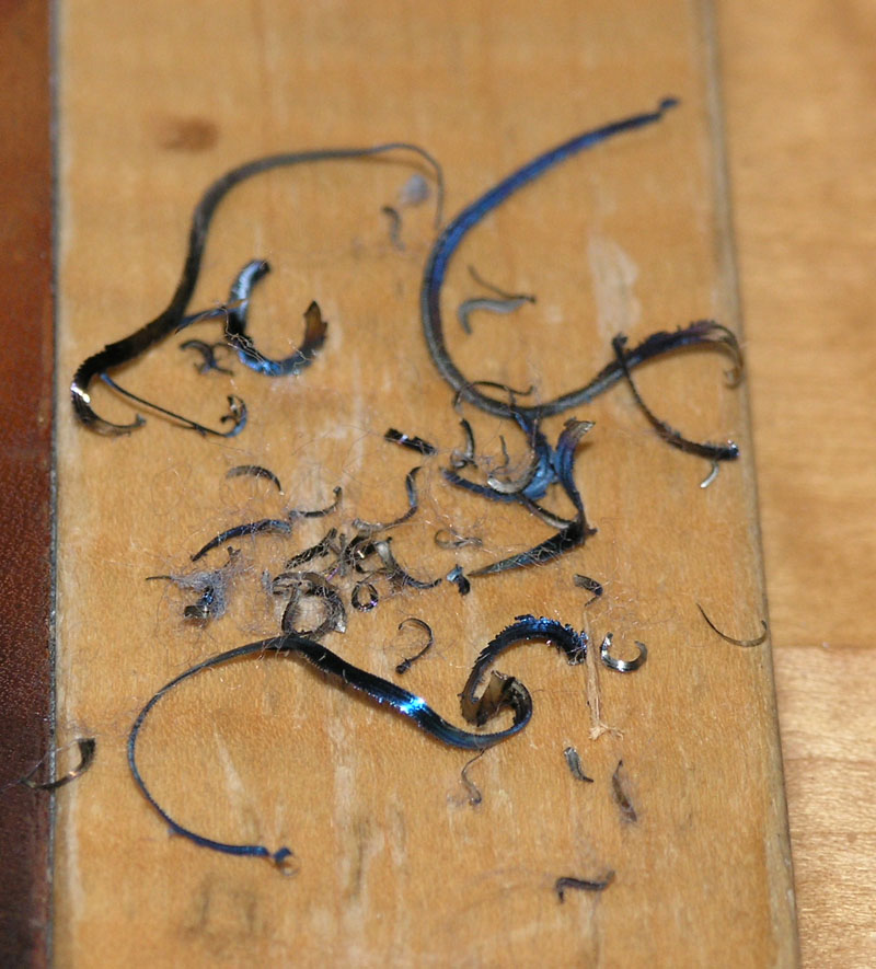
The other thing people have a hard time believing is that you can use carbide in hobby-class machines. I'm here to tell you it can be done and it works well. You need to track down the right tooling, and carbide won't be right for all situations, but it is amazing how well it works. Those blue chips are darned hot though, so don't let them go down your collar, and wear the right eye protection and follow the safety guidelines.
BTW, the chips above are not the greatest shape. I used a brazed carbide lathe tool in the flycutter, which is pretty common, but their geometry is not ideal for this application. On my lathe, I get perfect little blue 6's and 9's. However, despite the heavy blue chips, the surfaced table and the carbide tool were barely warm to the touch when I finished.
3/15/08
VMC Cast Iron Frame
Every wonder how massive a VMC's cast iron frame is? These machines are heavy. Take the Lywentech LZ-720, which weighs 6,000 lbs. Here is the unique cast iron frame for this massive machine:
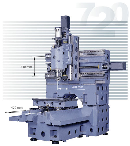
Beefy! Note the table only moves in Y. The head moves in X and Z...
Sieg KX1 Mini-CNC Mill In a Box
Isn't this a cool little machine:
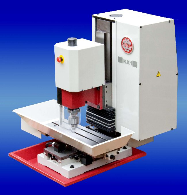
Thanks to John Stevenson who participated in the development testing for this machine for posting a picture of one. He says it differs from the X1 in having a fixed and heavier column, ballscrews on all axes, and limit switches. Power is a 3/4 HP 3 phase brushless motor under full CNC control with speeds from 100 to 6,300. You gotta love how it's set up at least to handle mist coolant. This is one very professional looking machine. I bet they'll sell quite a few, and this is just the beginning of turnkey hobby CNC from China. Apparently Sieg has a purpose-built factory just for this class of machine.
It did a very credible job cutting a model locomotive wheel in stainless steel, 304 no less:
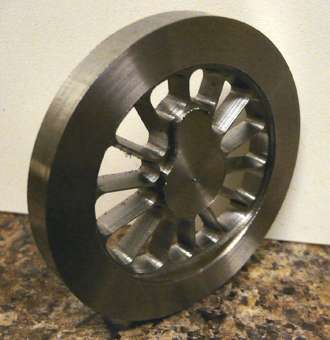
This was done at 1,600 rpm, 1.0mm depth of cut, and a feed of 90mm/min. Not too shabby for a little mill!
Built a Tailstock Camlock for My Lathemaster 9x30 Lathe
I've coveted one of these for a long time. I finally succumbed to the urge to make one after seeing the Little Machine Shop kit to install one on a 7x14" lathe. They're pretty simple, really. This one took me three or four hours to make. It sure adds a lot of convenience to using the tailstock!
3/12/08
Some Nice Upgrades to the HF Tool Grinder
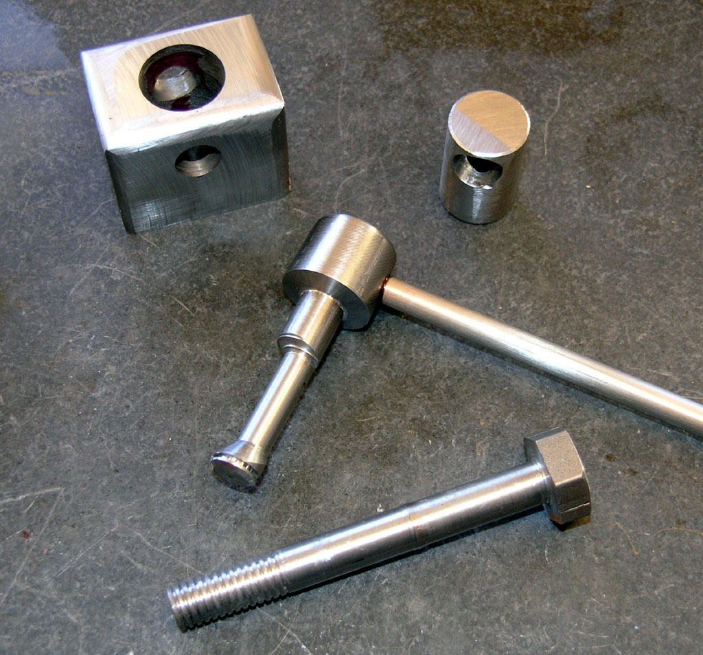
The HF Tool Grinders are an amazing bargain right out of the box, but with a few upgrades, you can really make one sing. Most people start out adding new wheels as the ones that come with the grinder are not so great. Don't get me wrong, they work, I used the originals on mine for a long time, but professional quality wheels are a lot nicer. To get a wheel swap done properly, you'll need to make sure the wheels are balanced. You don't want an unbalanced wheel spinning at 3400 rpm--if it flys apart from the stress someone could be seriously injured and there will certainly be some damage to your shop.
Jim Hubbel uses this rig to balance his new wheels:
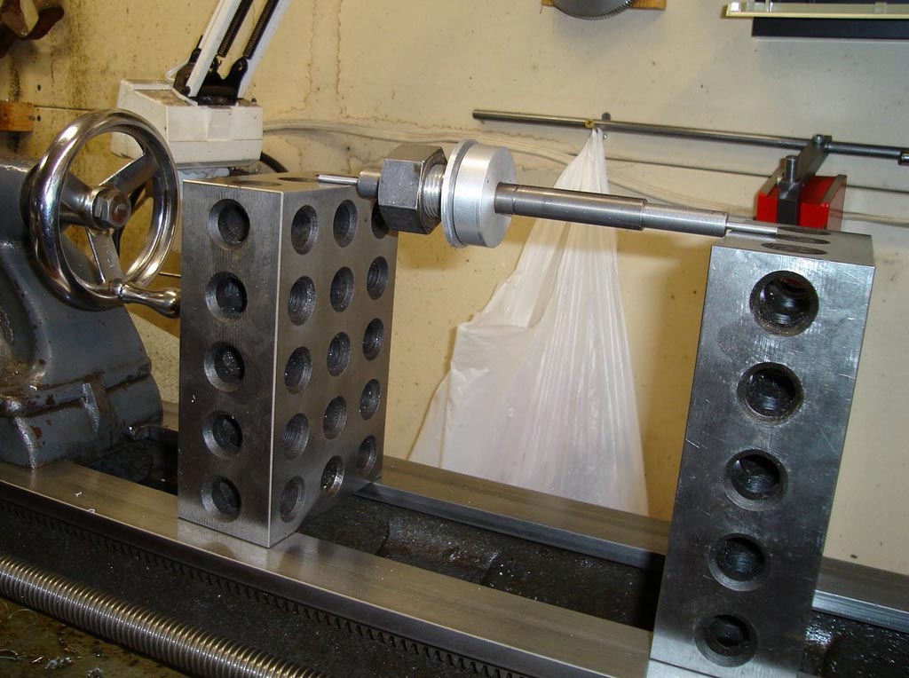
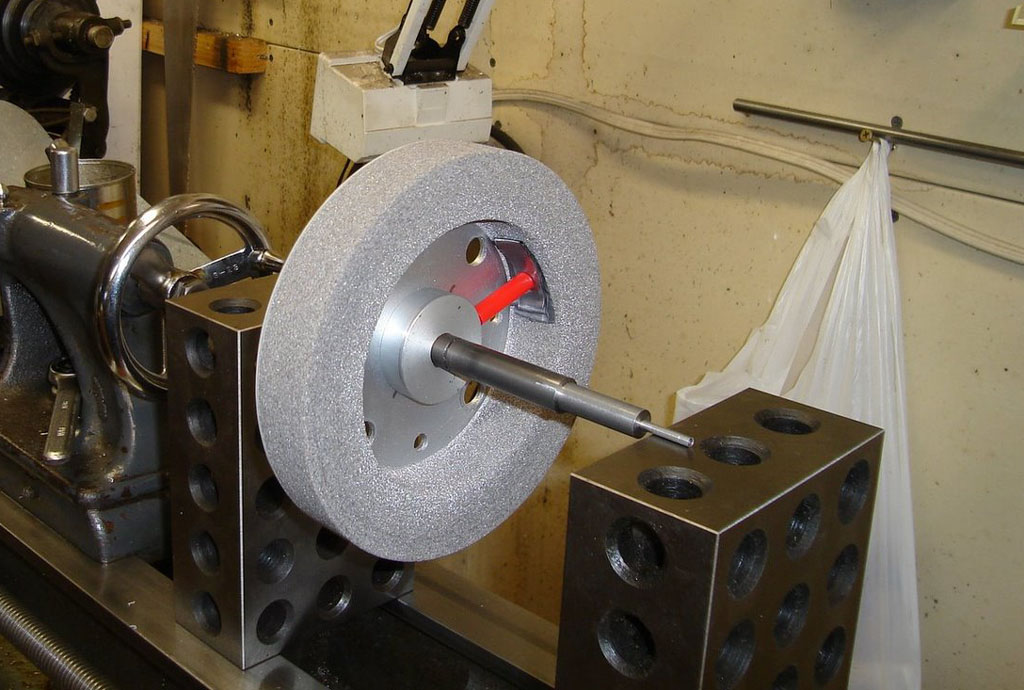
Quick, easy, and to the point. Looks like he'll epoxy some lead tape at the right spot on the wheel to balance it.
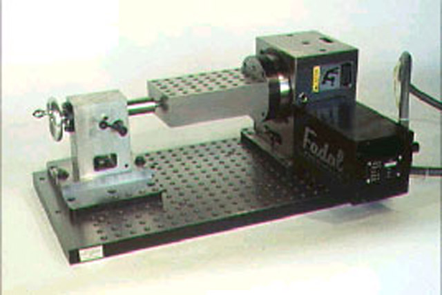
He also built this cool tool sharpening rig with a store bought XY table modified with a sensitive feed on the X-axis and a shopmade lathe tool universal vise:
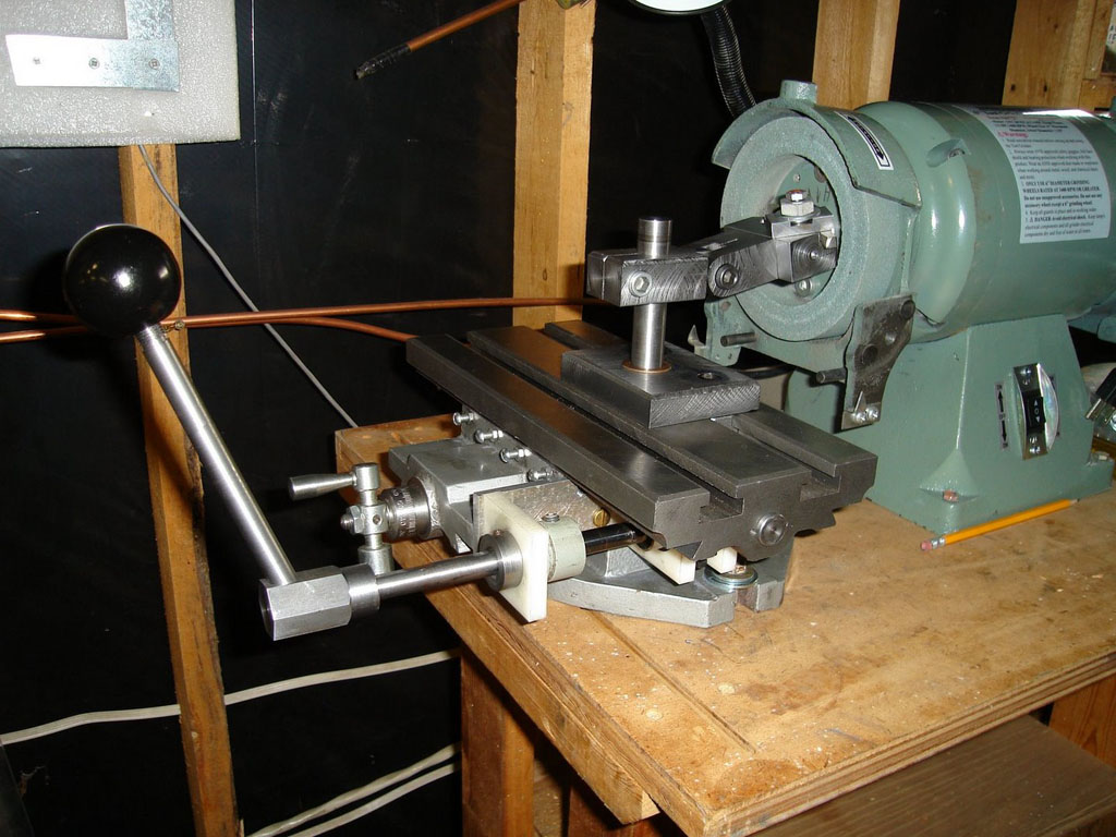
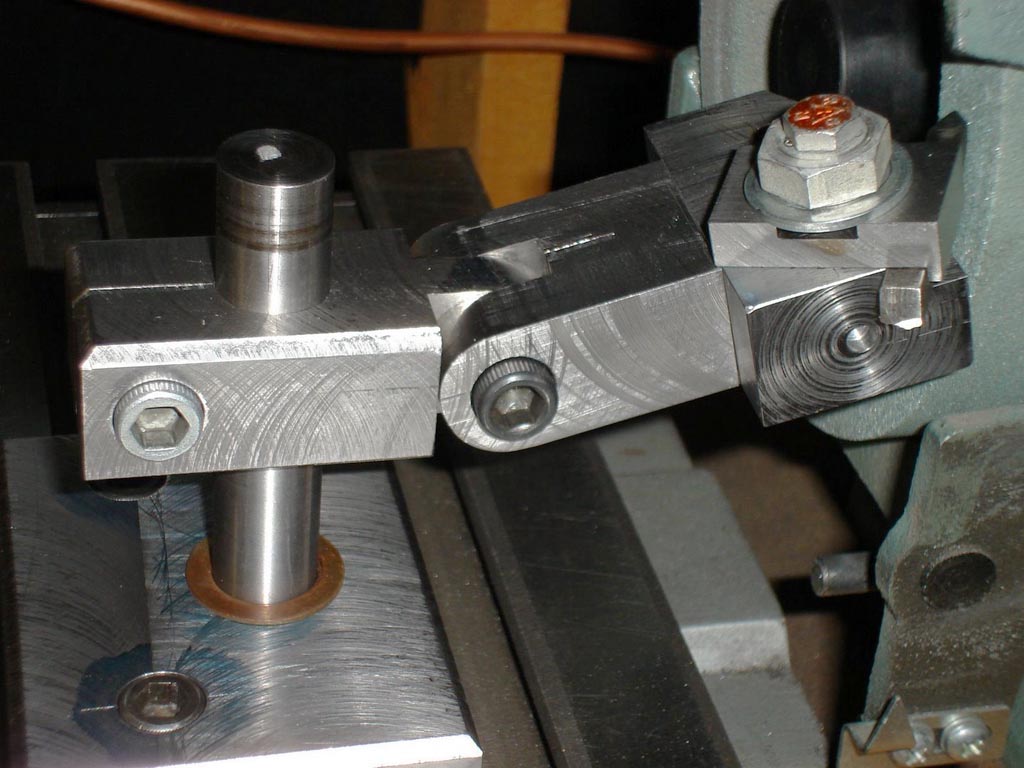
I've got to get working on a few of these gadgets for my own shop!
3/10/08
Wiggly Flywheels from Circles
A Rhino Cad design exercise:
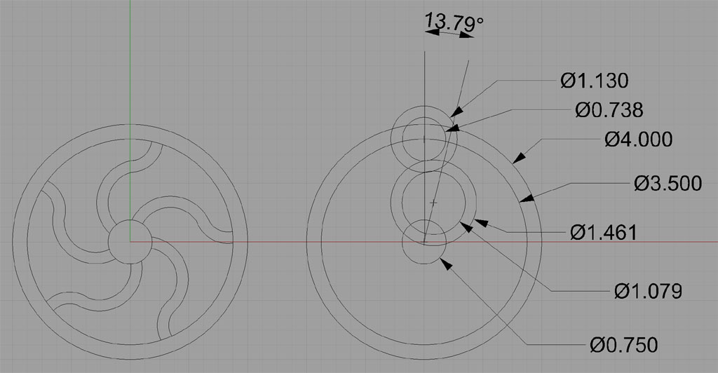
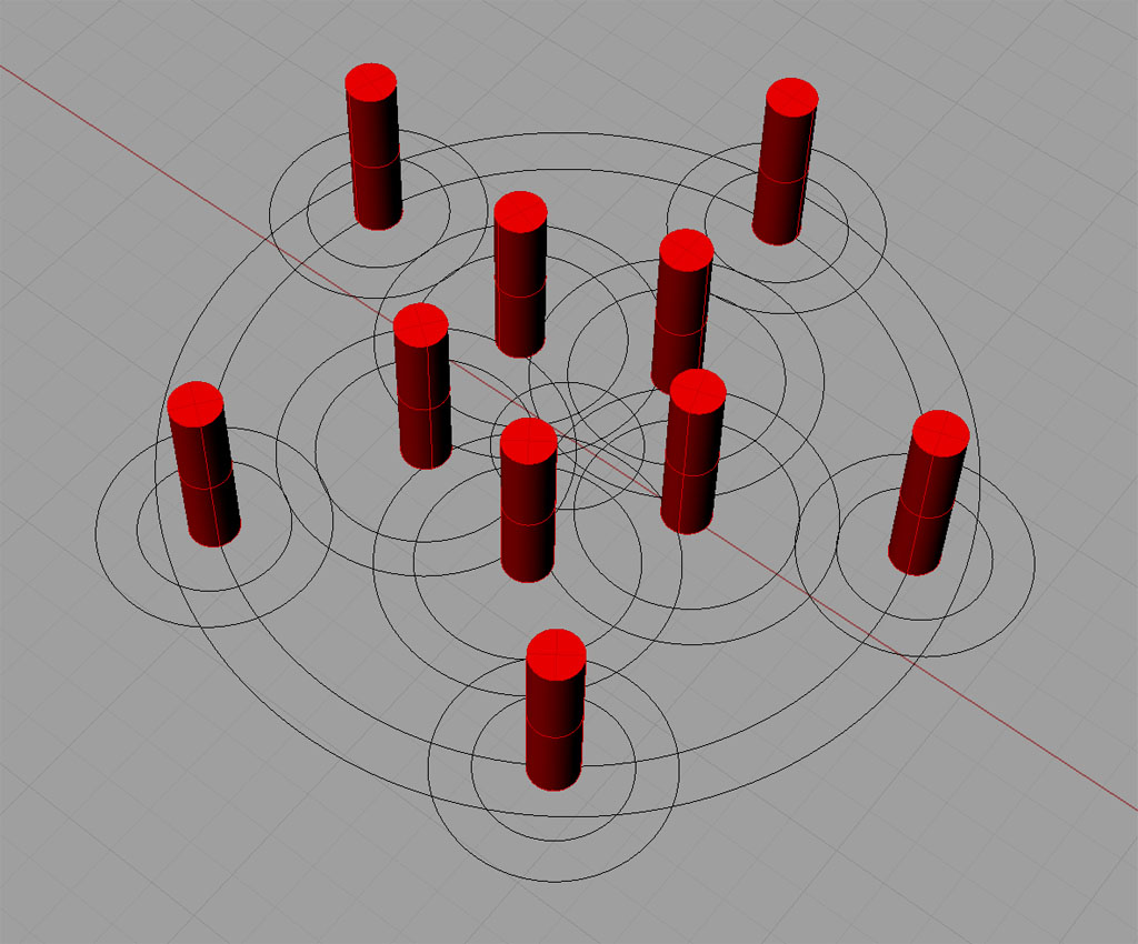
Layout of pins for a rounding over fixture to make the flywheel...
More Widgitmaster Tips: Use Your Height Gage on Mill Setups
When the Fidgiting Widgitmaster is working on a new design, it means there will be a blizzard of interesting things to learn. This time around he is machining the upright arms of his new router design, which required a bit of work to setup on the mill as they're not a simple rectangular shape:
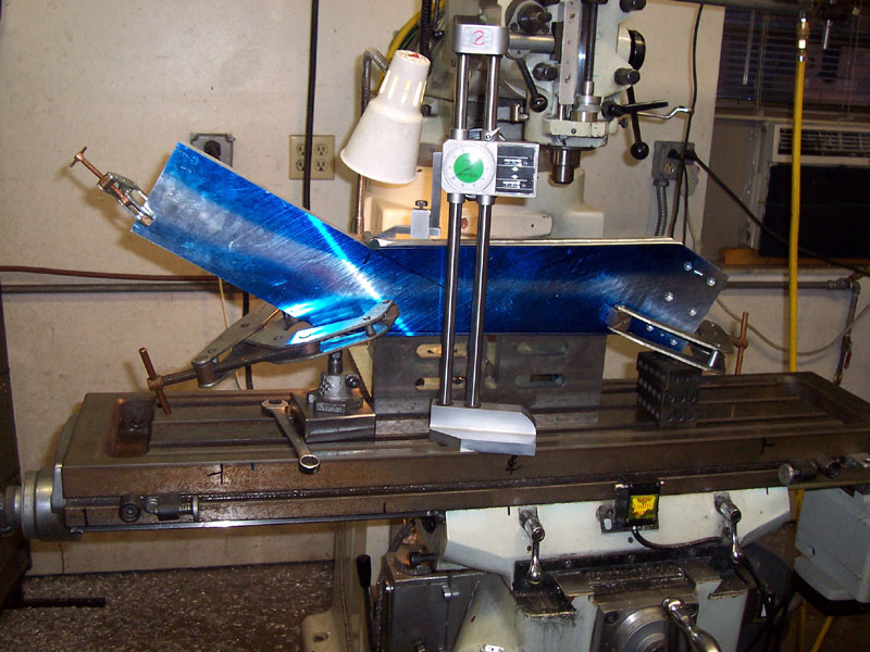
See the 1/2" pin right where the light is shining?
The challenge was to line up for a mill pass on a piece cut from the bandsaw. The top edge to the left and right were cut via the mill and then connected in the middle by a bandsaw cut:
So how does the height gage fit in? The mill cuts are precision cuts, done with a 1/2" end mill. Widget plases a 1/2" pin in the crook where the end of the mill cut is and then uses his height gage to see what that height is. Now for the other end (on the left), he can use the jack screw until the same measurement is reached on the height gage. Now he knows the piece is clamped on squarely. BTW, there are two uprights clamped together so they'll be the same size!
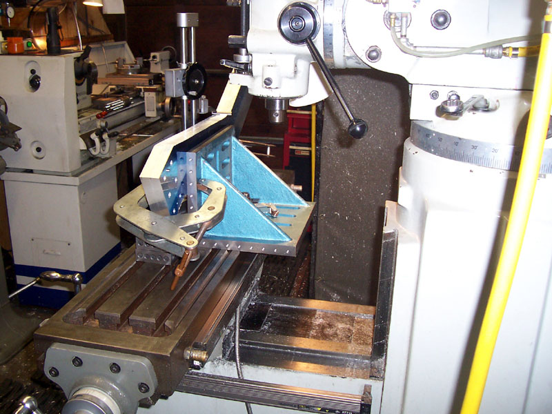
A little face mill action and we're there...
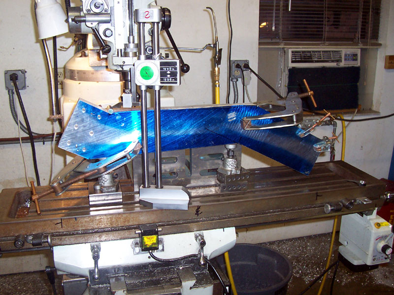
Flip and go again on the bottom side...
Use a Vee Block to get the precision dowel pins straight up and down and then hammer them to depth...
Wow, big uprights!
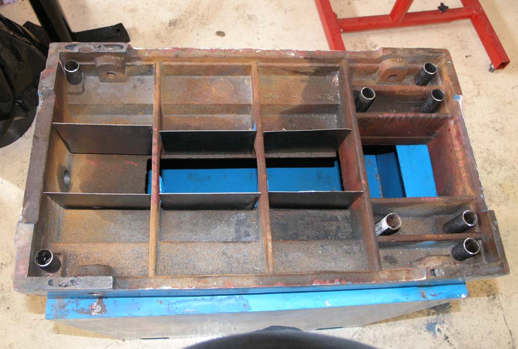
Epoxy Granite Update
Despite much procrastination, I have made progress on filling my mill base with Epoxy Granite. All the bays except the big hole under the column have been filled:
The Epoxy is still wet on the two small bays in the middle...
My biggest concern as I got to this stage has been leaking epoxy. The silicone sealed about 95%. The leakage has all been around the pipes, which are evidently hard to get a good seal on. They're not accessible. I tried to make it work by putting a big giant fillet of silicone on the pipe and then plunking it down carefully with no side to side motion. However, I still got a couple small leaks. They were not really a problem, except that such a leak on any of the 4 column mounting bolts would be a mess:
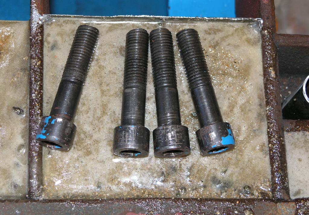
I can't afford an epoxy leak on the threaded holes for the column mounting bolts!
After much thought, I decided to insert the bolts partially in their holes and then pour candle wax on top until it was above the pipe/casting seam. The idea is that the wax would harden and keep the epoxy out. I used an ordinary cheap candle and torch to melt the wax:
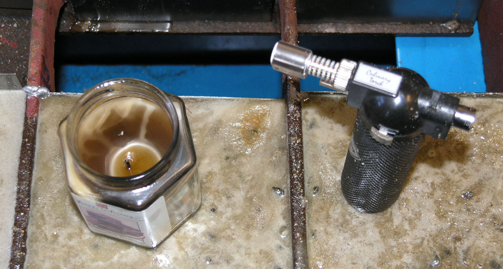
The process was easy, the theory was good, and the initial appearance also looks good. We'll see after the last epoxy has dried if I can get the wax out and the threads for the bolts are still good!
Next engineering challenge: figuring out how to mount my big central bolt that will add additional clamping to the column. I bought a 15" long 1 1/8" bolt and nut. Initially, I wanted to just cast the bolt into the base, but the thing is huge and will make handling the base awkward. I need to fab something up so the bolt is removable. This also means I'll have to put the base on leveling feet. Still thinking it over before I pull any triggers.
3/9/08
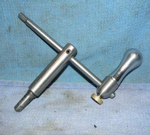
JCHannum's Chuck Key Speeder
What a nice idea:
3/8/08
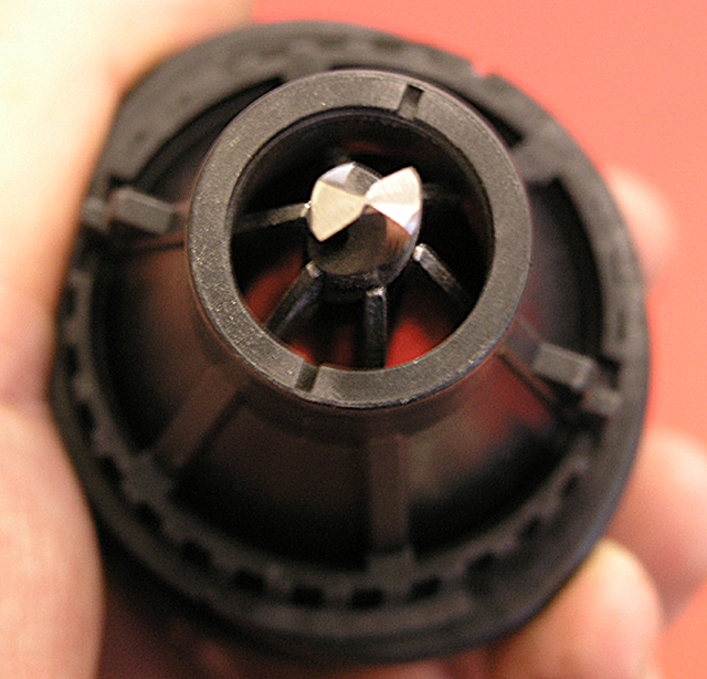
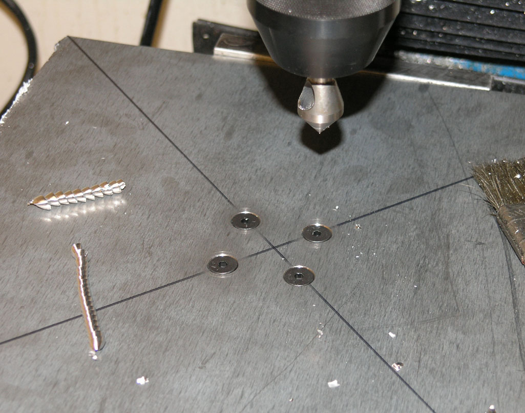
A Tale of Three Collet Chucks and their Runout
As part of my recent efforts to build a one shot oiling system for my IH mill, I discovered there was significant runout in my ER32 collet chuck setup that was causing me to break 1/8" ball end mills right and left. So, I promptly concluded this was because I had a cheap ER32 chuck I'd bought from 800watt on eBay, and it was time to shell out for nicer chucks. I found 2 Bison chucks with R8 shanks on eBay, and promptly bought them. Bison is a great name. Later I learned I couldn've bought Maritool chucks for less (also a great name), but I digress. The chucks arrived today and I wanted to see what the runout was. Here's what I found out (hint, the Bisons have lower runout than the cheap chuck, but the cheapie wasn't bad and this wasn't my problem):
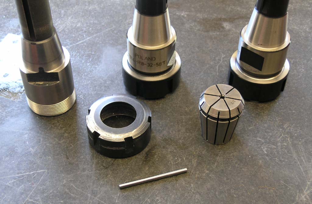
2 collet chucks, a 1/8" collet, and a 1/8" pin gage. I checked the pin carefully on the surface plate and its straight and true. Yep, I kissed the vise with the old collet chuck, but it was just the aluminum jaws so it rubbed a little of the black oxide off.
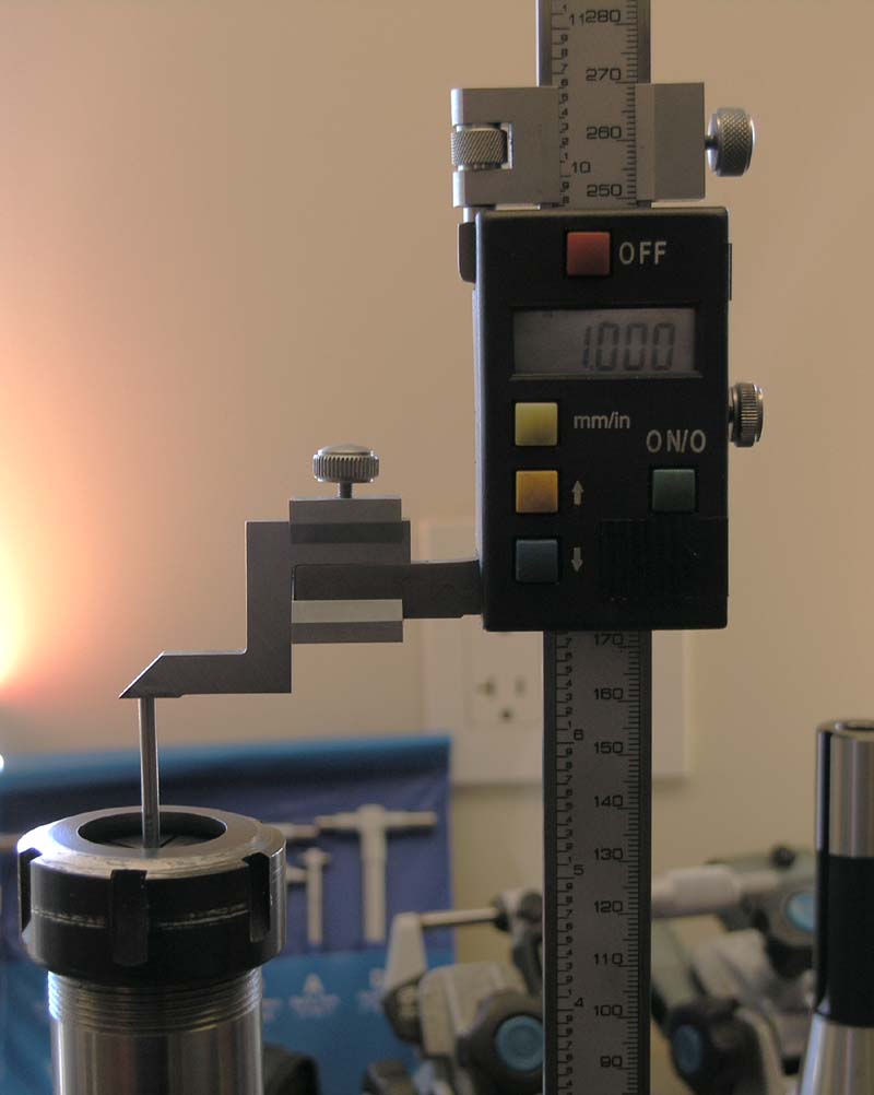
I wanted to measure the runout of the pin 1" below the chuck on all chucks to ensure I was making an apples to apples comparison. BTW, what's wrong with this picture, whcih I staged too hastily after the fact?
(The collet is not snapped into the nut!)
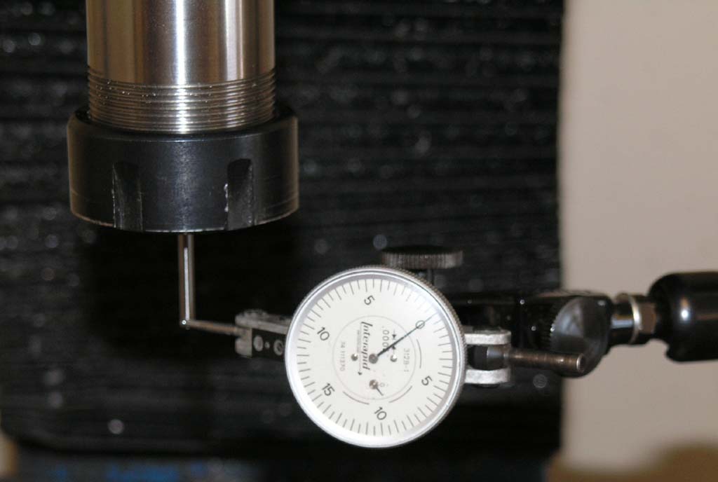
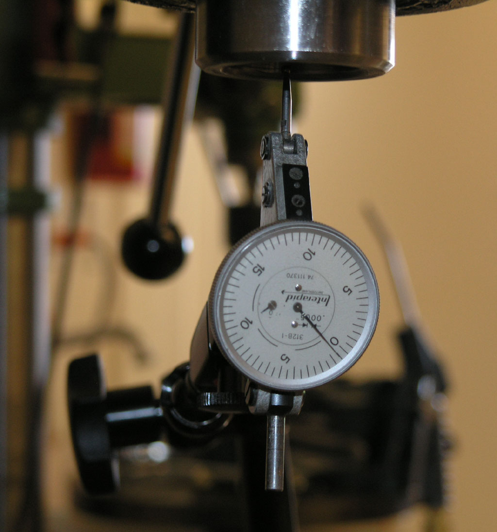
Zero the indicator on the pin, and turn on the spindle, lowest rpms, to see what the swing looks like...
Pretty nasty on my cheap chuck: 6 divisions on the 0.0005" indicator = 3 thousandths. Yuck!
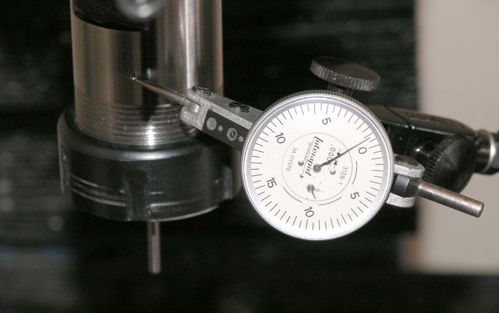
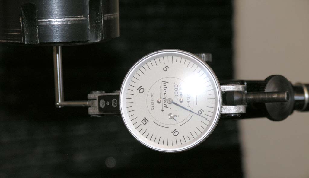
Yet the outside of the chuck is circa 0.00075" runout. Hmmm...
Better check the R8 taper itself: 0.0005" runout...
Okay, so here is what I got:
- Inside of spindle taper: 0.0005" runout
- Outside of collet chuck runout: 0.00075" runout
- Pin runout on both cheap and Bison chucks: 3 thousandths
Conclusion: Bad collet, bad!
Doh! Now I gotta shell out for a new set of ER32 collets, which are not cheap! The best deal on :"nice" ones I found was Maritool--Bisons were quite a bit more money. FWIW, Maritool is a company many on the PM boards swear by, and they're pretty picky. So I ordered the Maritool collets. Will report on them when they arrive. BTW, Mari has a great deal on ER32 collet chucks too!
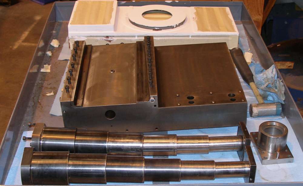
Time For Another Widgitmaster Installment: Big Router Tricks
Widgitmaster from the CNCZone has been one of the best sources of tips I have ever found. He documents his router building projects extremely well, and as a retired professional machinist, he knows a lot of tips to pass on! Lately he has been writing about a new big router build up. It's a really cool machine that is much larger and beefier than his earlier projects:
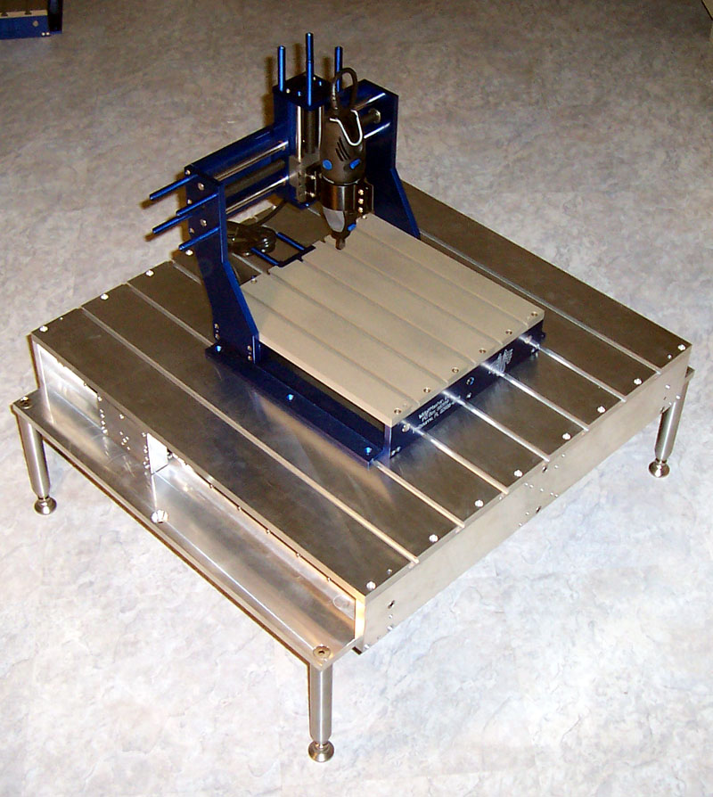
His normal "production" router is sitting atop the table for the new one. My little Widgitmaster router would fit on the production router!
Let's run through just some of the photos I found interesting on his build log so far:
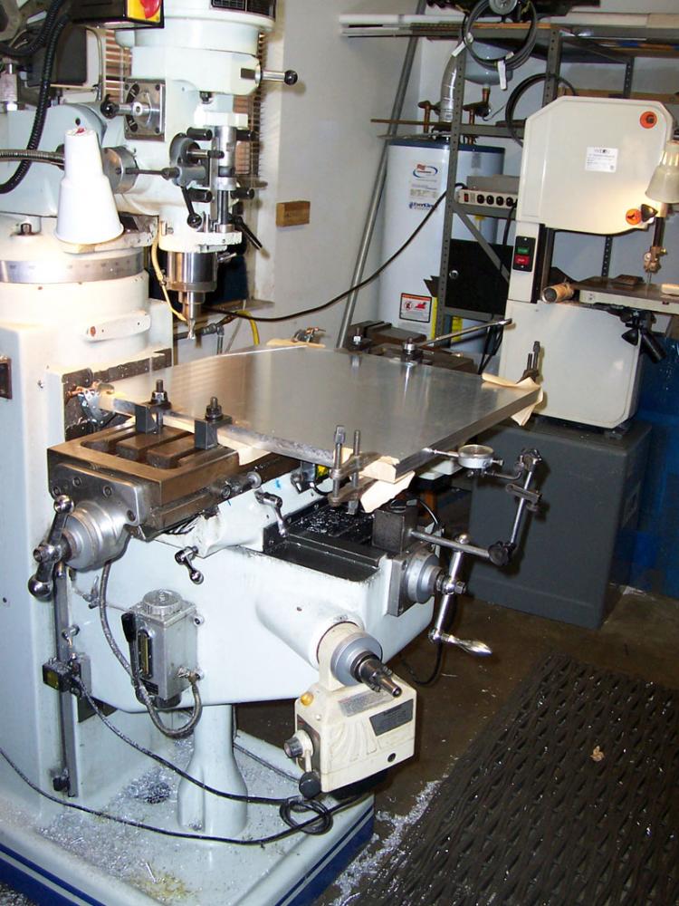
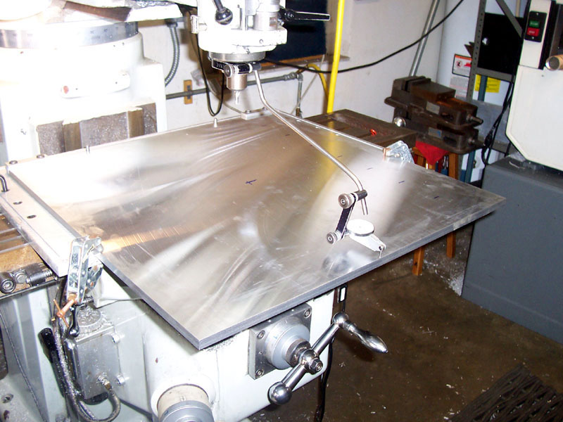
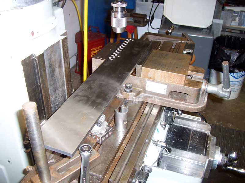
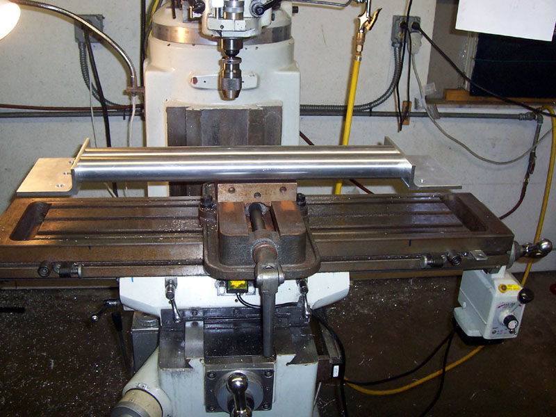
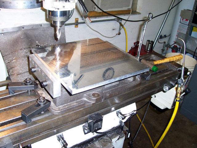
First job is to square the 24" x 24" MIC-6 plate that will serve as the table. Dang that's a big ole plate on that mill! In fact it is 2 plates stacked and clamped together. Note the use of soft material to protect the finish on the MIC-6 plate as wel as additional clamps, and the dial indicator to get the edge aligned with the axis...
Squaring the edge...
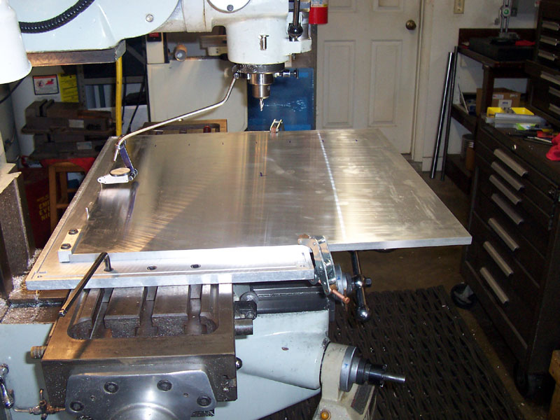
Now he's mounted a tooling plate with a stop to locate the plate. Note the Indicol of Doom!
A little better view of the Indicol of Doom dialing in the far edge...
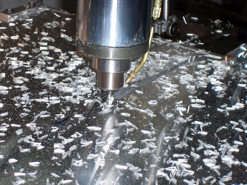
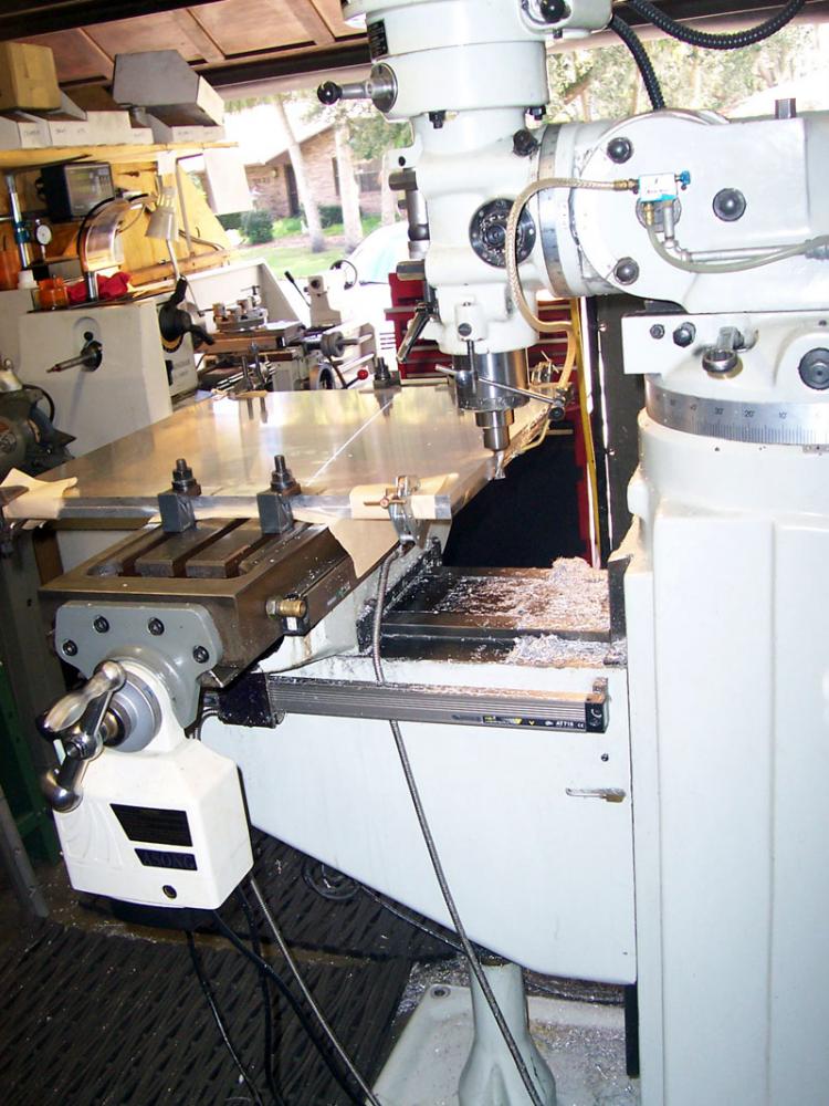
Now we're cutting T-slots. First use a regular end mill to slot. Coolant mister is firing at the trailing edge to clear chips...
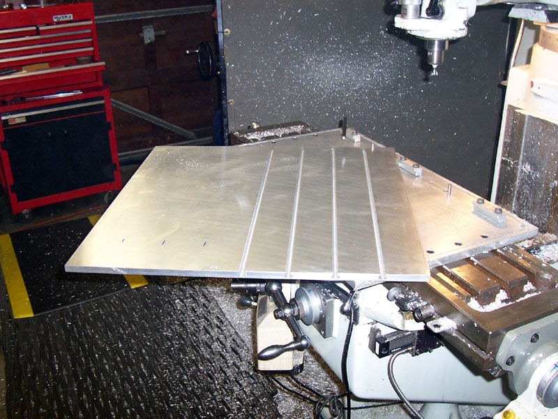
Got some cut. Now he can flip the plate around 180 degrees and cut the rest. Note that this rig is keeping the cutting from getting far off the edge of the table or the axis. Keeping the cutting over the center of mass of the mill means better rigidity!
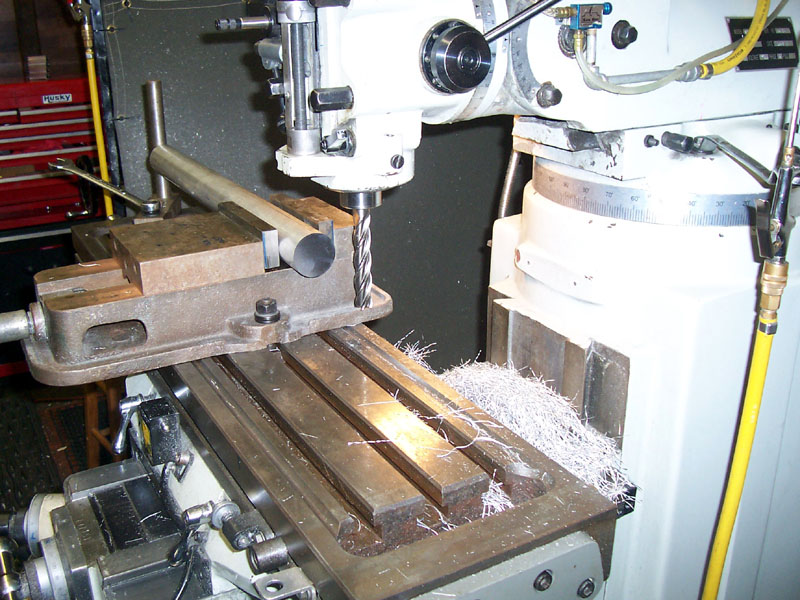
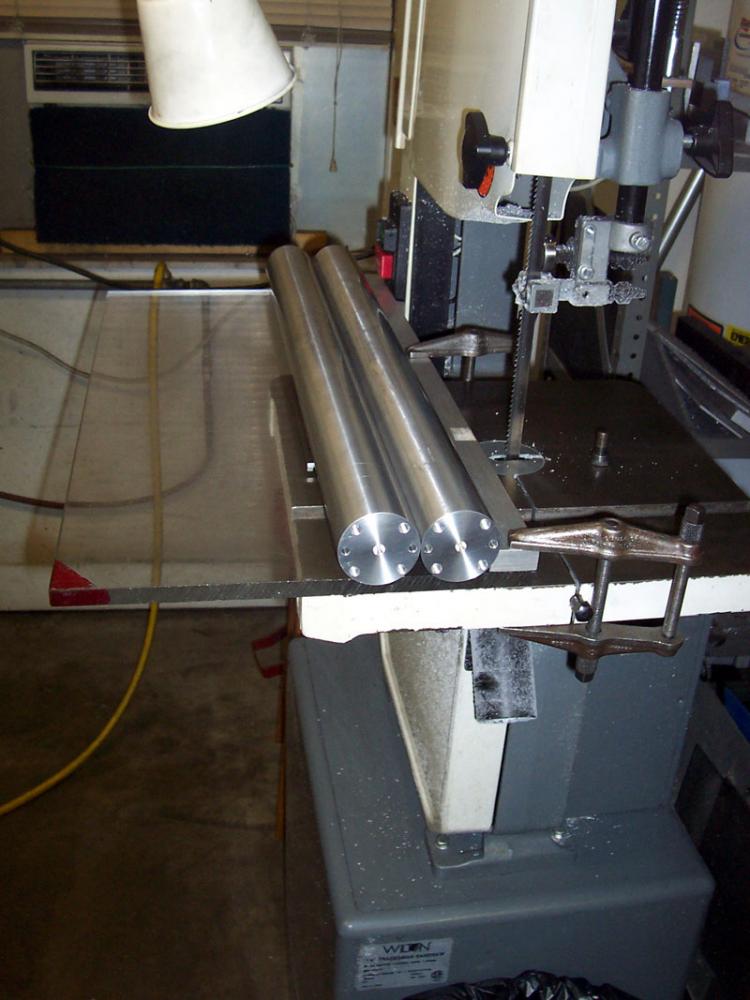
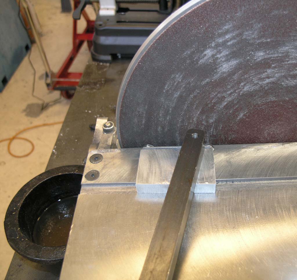
That massive rod will serve as a Y-Axis rail. Widgitmaster is cutting the rod to precision length. Note the big shop made stop on the table at the far end...
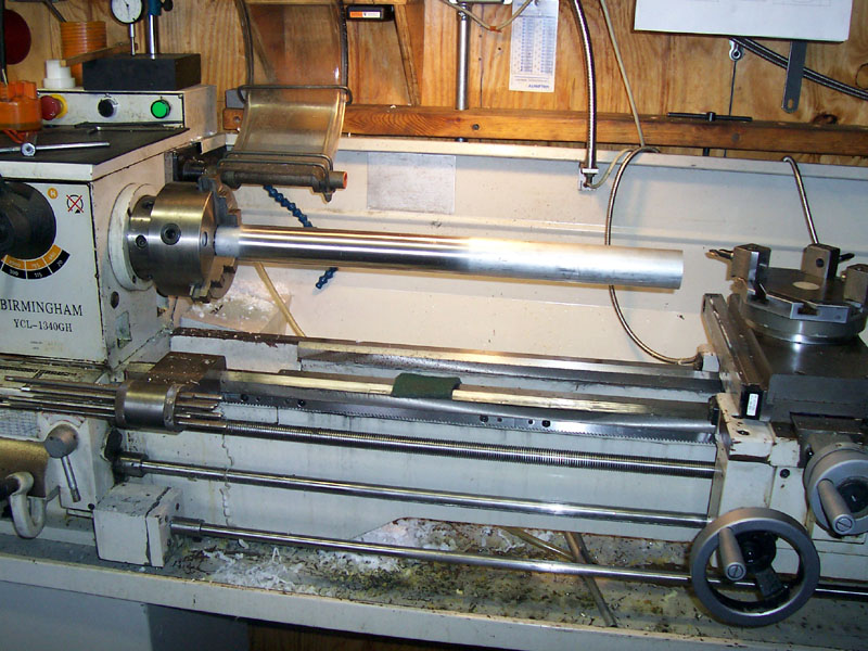
Here he is using his lathe to give it a polishing with Scotchbrite pads...
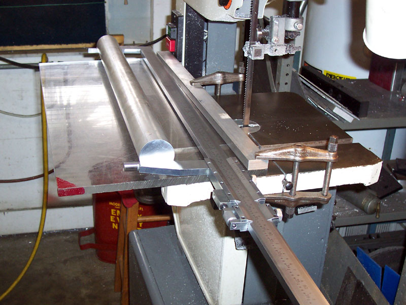
Next, the Big Caliper of Doom is used to check the length is correct. A plate clamped to the bandsaw with a fence provides a handy additional work surface...
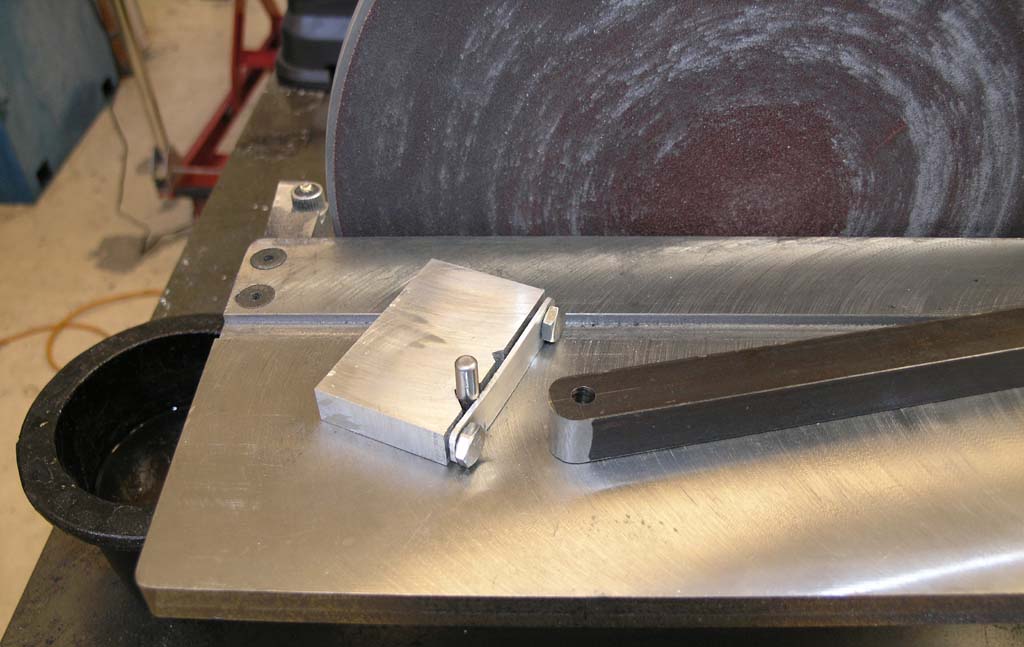
There's a closer look at that table stop. He's got a machinist's jack under there too. Widget likes to use closed end wrenches as removable handles on his tooling and mill I've noticed. This plate is going to be part of a fixture he is building...
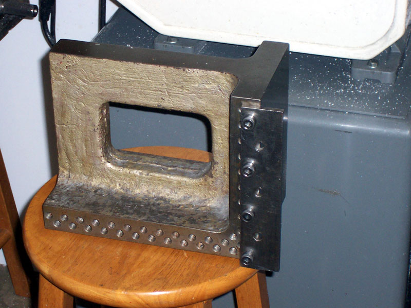
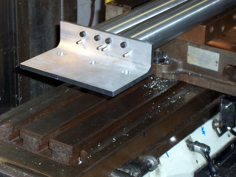
Note the hole pattern in this big ole knee block. There's a little piece of Widgit tooling bolted to the side there already...
Does that hole pattern look familiar?
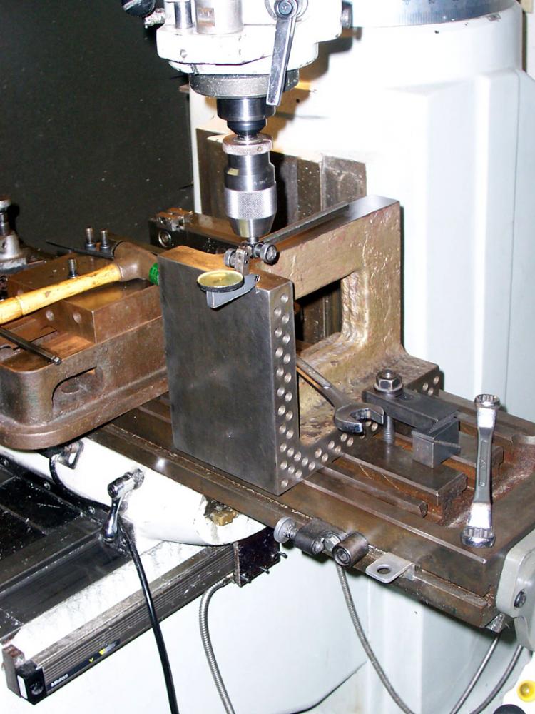
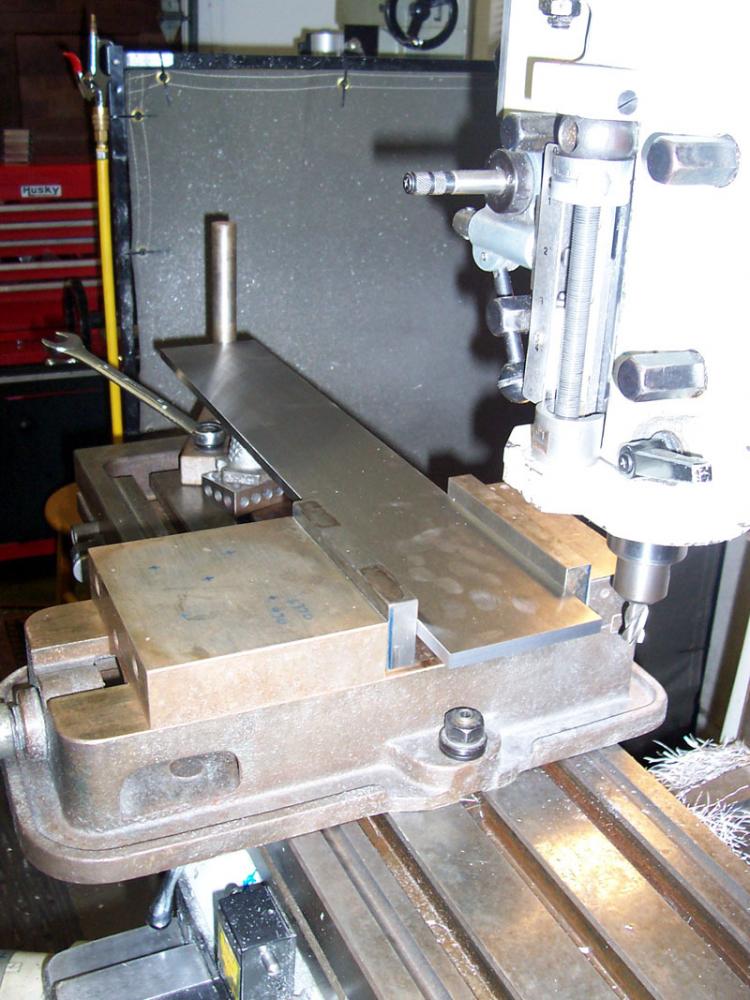
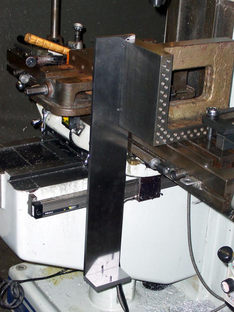
Now dial the face of the big angle block in square. It's hangling over the edge for clearance, Clarence...
Widgit is drilling and tapping the end of the long piece. There's also 2 drilled and reamed holes for precision dowel pins. Bolts are not for alignment, they're for clamping. The dowel pins ensure precision alignment. Note the tap holder--essential for getting things straight up and down! I'm slightly surprised he isn't power tapping it, but maybe this is more precise and it's certainly less likely to break a tap in the steel fixture. Note the copious use of Kant-Twist clamps. Those things are a God-send!
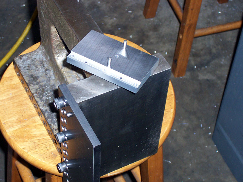
This handy little "Guzinta" will be used in a second. For now, note it has two bolt holes, and two dowel holes in the stepped end for precision alignment...
There is the "Guzinta" on the bottom. Why is it called a "Guzinta"? Because it "goes into" right there! So now we have extended the precision planes of the mill's axes in a nifty way with this fixture.
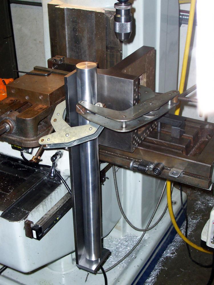
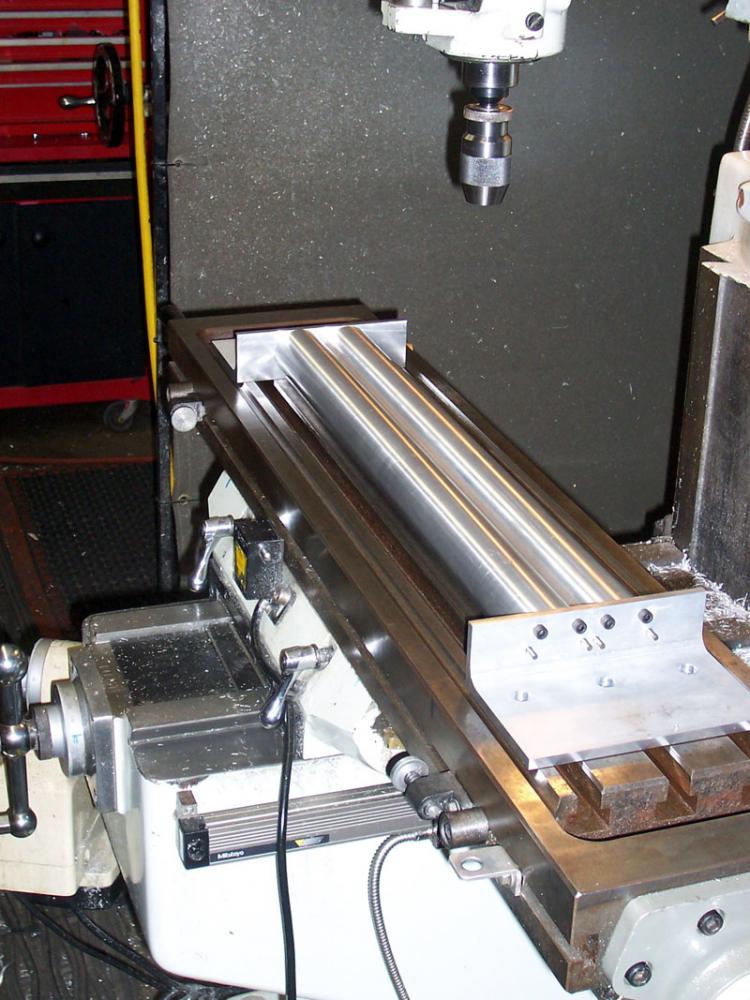
So now we can mount the Y-Axis rod in the angle of the precision fixture...
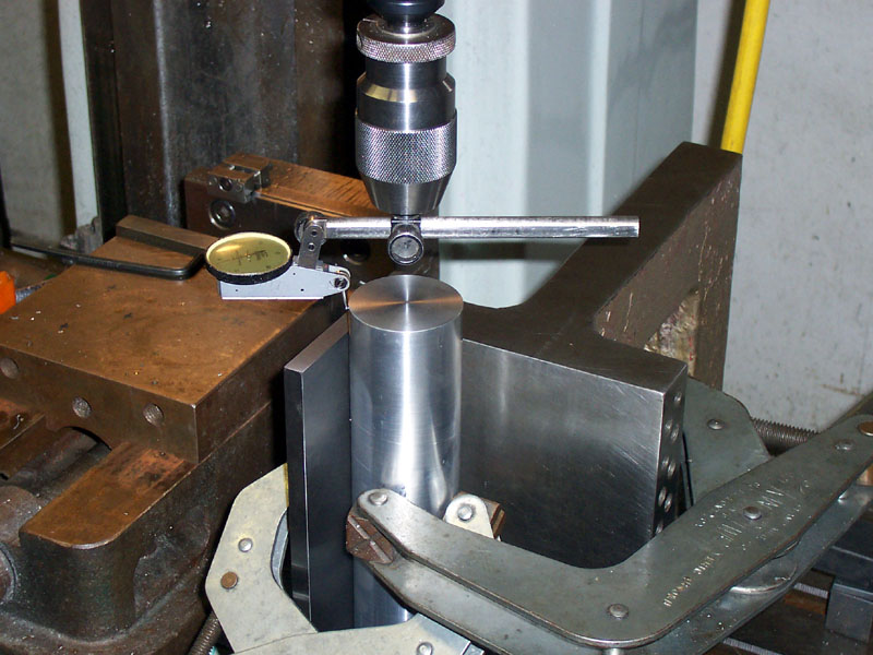
We dial in on the center of the Y-Axis rod...
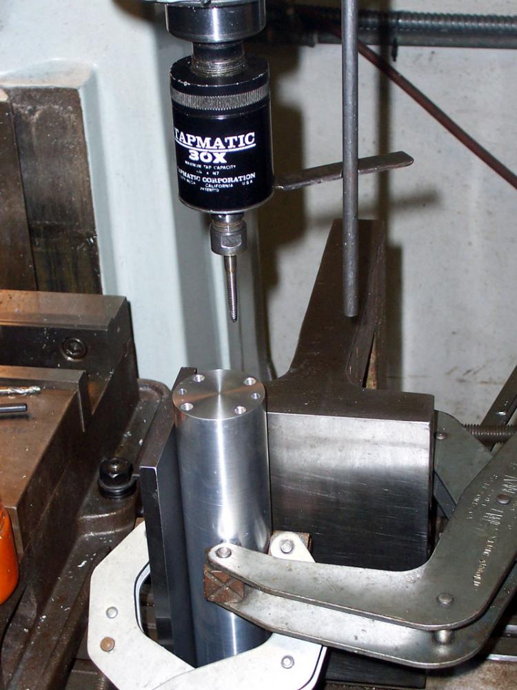
Drill and Tap...
Got 'er done!
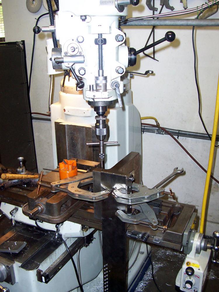
Next Widgitmaster built a precision fixture to hold the Y-Axis rods for support hole drilling.
Of course everything is properly square and precise, and the Y-Axis rods are located with dowel pins and clamped with bolts. Top notch precision craftsmanship!
Whole works will be dialed in true on the table, but we have to wait. Widget hasn't received some parts and doesn't know the hole spacing yet!
3/6/08
How Big is Your Boring Bar?
RJ Newbould's bar from the PM boards totally rocks!
Lots o' setscrews hold the cutter in place in the slot. The bar itself is its own QCTP holder!
Height set is here. Newbould ground the head to the right height for this lathe and it is Loctited in place.
More Positive Rake Goodness: CCGT Boring Bars
There's a good thread on PM right now about these inserts for boring aluminum:
That's a lot like my favorite CCGT "crown" shape:
I'd love to try those inserts on a boring bar (and not just on aluminum)!
Press Tooling: Punches, Bending Brakes, et al
I'm planning on building some tooling to make my 45 ton press more useful. I want a press brake attachment for sure, but a punch and die attachment would be cool too. Towards that end, I got an eBay deal on the raw materials to make one. This is a Danley punch and die set that cost me $30:
I figure just the materials alone were worth 30 bucks. The thing weighs almost 70 lbs! I got two of them. I figure I can use the linear bearing arrangements to make a punch and a press brake, albeit with some significant redesign.
A Simple Rounding Fixture for the Grinders
While waiting for epoxy to cure on my IH Mill Base, I wanted something to tinker on. I came up with this simple rounding fixture to use with my grinders:
Trivial to make, but it works well. See my grinding fixture page for details.
HSS vs High Positive Rake Turning Tooling
I can get pretty much everything done that I need to get done with my carbide insert lathe tooling. But, there are persistent rumors out of the HSS steel camp that it's better:
- Many claim a better surface finish.
- There is a claim that finer "dust" cuts can be taken that allow for greater precision.
Certainly you can make tool shapes in HSS on the grinder that don't exist in insert form too. I recently made a form tool in order to make a new pulley for the window regulator on my brother's Audi TT. It was great. Would've taken longer to make the form tool than the pulley if I hadn't decided to cannibalize an old cutoff tool I had ground a long time ago. I like to learn new things, so I keep fiddling around with HSS off and on, seeking enlightenment. I kicked off a thread over on HMEM about sharpening, but so far I haven't learned too much. The assumption of most of the contributors is that I need to start at the very beginning, and I'm past that point, I want the second semester course. I have ground HSS according to the classic formulas offered up in places like South Bend's Running a Lathe book. There has to be more than that, else I won't be bothering much with HSS because it doesn't perform any better than insert tooling.
At some points reading the discussion, I sometimes wonder whether the two camps have any awareness of what the other is doing. Do the carbide guys do enough HSS to realize its advantages? My assumption is they don't, and I'm trying to remedy that in my own case. But the converse is also true: do the HSS guys know what really good carbide tooling is capable of? I read so often from machinists who say there is no point in carbide tooling, or worse, that it can't be run properly on anything but super high performance Monarch 10EE and Hardinge lathes. That's total hogwash, period, full stop. See the Cookbook section for information on how to use carbide tooling, what to look for, and how well it works.
Given my concern that the two camps don't talk, I fear there is a real possibility that there may not be any magic in HSS, and it will therefore remain seldom used in my shop. After all, a new insert is $3, it takes seconds to install, they last a long time, and they have multiple edges you can use. If the HSS doesn't perform convincingly better in some way, why bother? It isn't saving much money (unless you object to the price of indexable turning tools), and it does take time as well as its own tooling costs (tool grinder, diamond laps, wheels, etc.).
Meanwhile, I embarked on yet another trial with HSS. There was some interest in the super-high positive rakes I use, which I mentioned on the thread. There was also continued admonition that HSS isn't hard, that there are no particular secrets, and that one has to just do it. Thank you Nike!
Accordingly, I compared performance of a couple of HSS tools with the CCGT insert tooling. Here is the summary visual result:
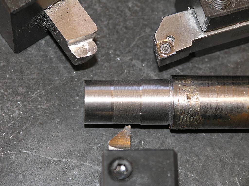
We have 2 fairly classic shapes in HSS. At the top left is a very large radius finishing tool. It's set up to cut right to left (towards the headstock) rather than the usual "cut either way" because I needed to get a little closer to a shoulder with it for one project. At bottom is a classic HSS, small radius, high rake "knife tool". It looks burnt to a crisp yellow, but that is a lighting effect. You can see the CCGT inset at top right looks yellow too, and I can assure you it is silver. Each tool is more or less pointing to a section of mild steel rod so you can compare the surface finishes. It's extremely hard to capture the nuances in a picture, but visually, the best finish is the HSS finishing tool, followed by the CCGT insert, followed by the knife tool. All in all, I see perhaps a very slight advantage in the finishing tool, but otherwise, the CCGT does the job.
I'm still waiting to learn how to best carbide with HSS.
3/5/08
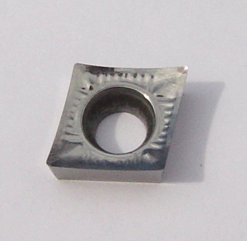
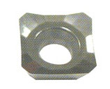
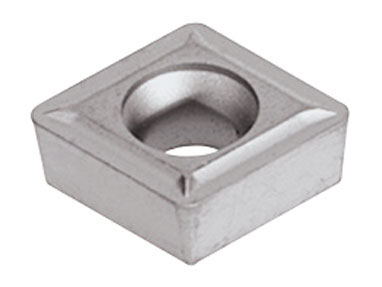
High Positive Rake Turning Tooling: CCGT
The very high postitive rake inserts I like to use look something like this:
The little buggers are hard to find, though, so I spent a little time doing some research. For some reason, they tend to be identified as "CCGT" rather than "CCMT". According to ISO, all the "G" is supposed to mean is that the insert was made to tighter dimensional tolerances. It is a plugin for CCMT. Likewise TCGT fits TCMT for triangular inserts used on something like a boring bar.
I went deep into the manufacturer's sites to track down this insert shape, because that's the key. Regular CCMT's often have some positive rake, but nothing like this. What I discovered is that the major insert makers have a special line of this style insert:
Valenite CCGT-1L
Each one has a slightly different sales pitch about why you'd use the insert. Iscar is pushing them as offering such a fine finish for aluminum that no grinding is needed, for example. The recommended materials even vary across the lines. What started out as an aluminum super finishing insert can be had in formulations that extend to high temperature allows, stainless, and other possibilities.
Now the bad news. Since they aren't nearly as common as regular CCMT's, and they seem relatively new, they cost more money. Carbide Depot has a page offering many of these inserts. You can find them much more cheaply on eBay, but they are often poorly identified. My rule is if I can't clearly see the high positive rake design in the picture, I won't take the chance on eBay. By shopping carefully, I've managed to buy 20 or so of these inserts, which will last me for quite a while.
Thoughts on Positive Rake with Indexable Tooling
Positive rake is generally goodness, especially for home shops. Positive rake reduces cutting forces, and that's important for machines that may not be as solid as a big VMC to start with. There are two ways to achieve positive rake. First, is to build it into the carbide insert itself. Consider the following CCMT insert:
Slight positive rake before we hit the chipbreaker...
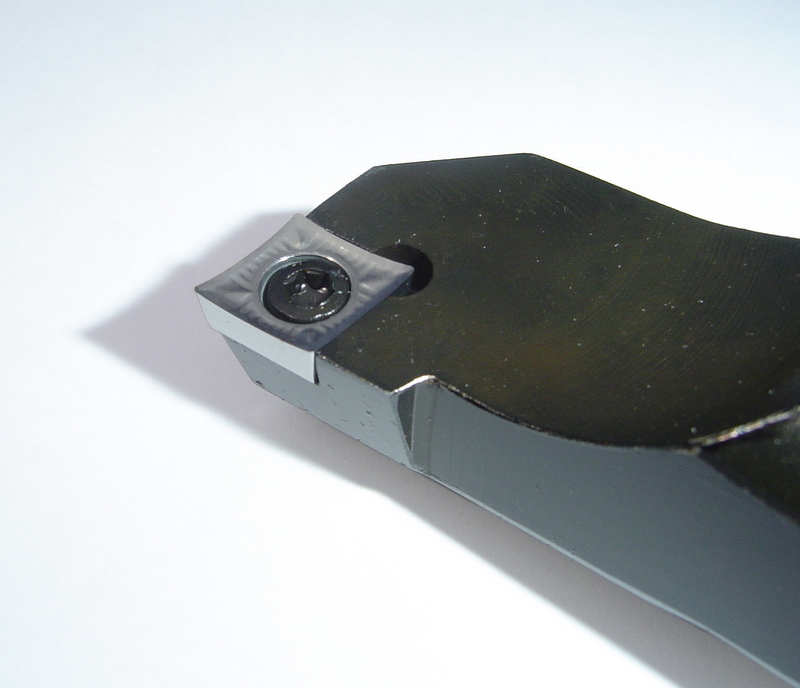
It has very slight positive rake as the surface dips down from the cutting edge as you move towards the center before you hit the chipbreaker. It's kind of hard to see here, but trust me, it's there. Now let's look at this CCGT insert (compatible with the CCMT, but ignore the CCGT designation and focus on the shape):
Huge built-in postitive rake!
This insert is designed for aluminum finishing. Note the huge positive rake that's built right into the insert! These little jewels are hard to find, but they will put an amazing finish on aluminum and they work quite well on steel too. Their disadvantage is the edge is thin, so they can be a bit brittle.
The second way is to angle the insert to increase whatever rake it may already have. Some inserts, like TPG's, are flat on top, and have no rake. You have to angle them to get any. Here's a triump of marketing over substance. The following face mill is advertised as having "90 degrees positive rake":
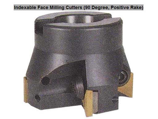
90 degree positive rake!
It uses TPG inserts which are mounted dead vertical. There's no positive (or negative) rake at all for this face mill. It's neutral. Now consider this one that is advertised as having "75 degrees positive rake":
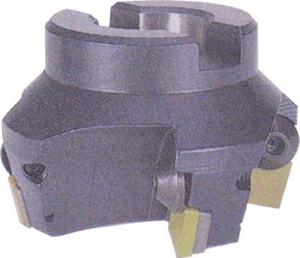
Now we can visibly see some rake. The inserts are "laid back". That means lower cutting forces and often a better surface finish. Incidentally, these two are both available cheaply from CDCO. Another incidental is that the 75 degree rake face mill is the one Widgitmaster has told me he uses most often, and I can tell you his surface finishes are superb!
3/4/08
Epoxy Granite Mud Pie Test Was Successful
Here's what we got the next morning:
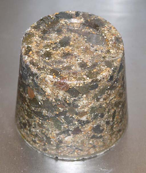
Test was successful!
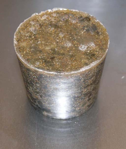
The test was successful. The aggregate is embeded in the epoxy. The slug took a very accurate impression from the cup--you can even see scratches made in the plastic by the gravel's sharp edges are faitfully reproduced. I suspect creating a precision surface in this material is easy if you have a precision mold. The material released easily from the plastic cup--just a couple sharp raps on workbench and it dropped right out. The ugly parts are at the air-epoxy interface from the top of cup. There are various approaches to eliminating the air bubbles, but it doesn't seem like there were many bubbles trapped in the material from the mixing process--they're all at the top. A quick pass with a heat gun is rumored to be the quick trick to get rid of those.
At this point, I can't see much point in monkeying with success. It may be that a 10% epoxy formula would be better, but this will work just fine for this project. I plan to keep Epoxy Granite in mind for other projects. I understand it sets up with an accuracy of 0.001" on top if you get rid of bubbles, so you could make a surface plate from it.
Also consider the aesthetic potential if you embed something more interesting than pebbles and sand to make Micarta.
A Tip:
There are a couple minor imperfections, total area maybe 1/4 square inch, where the gravel shifted and prevented good epoxy contact with the cup. Of course I turned the sample around so no ugly spots were photographed! If I were making something where such ugly spots mattered, I think the answer is to paint the mold with a thin layer of epoxy, say 1/8" or so, before introducing the epoxy granite mix. That would ensure a little safety margin. With the pumps, it's real easy to mix a little epoxy in a cup and use a chip brush to apply it.
3/3/08
Ongoing Experiment Filling Machine Castings With Epoxy Granite
I've reached the mudpie stage in my Epoxy Granite project:
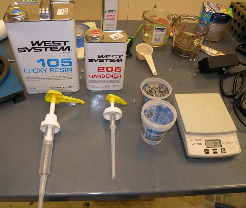
West System epoxy resin and other goodies needed to mix the mud pies...
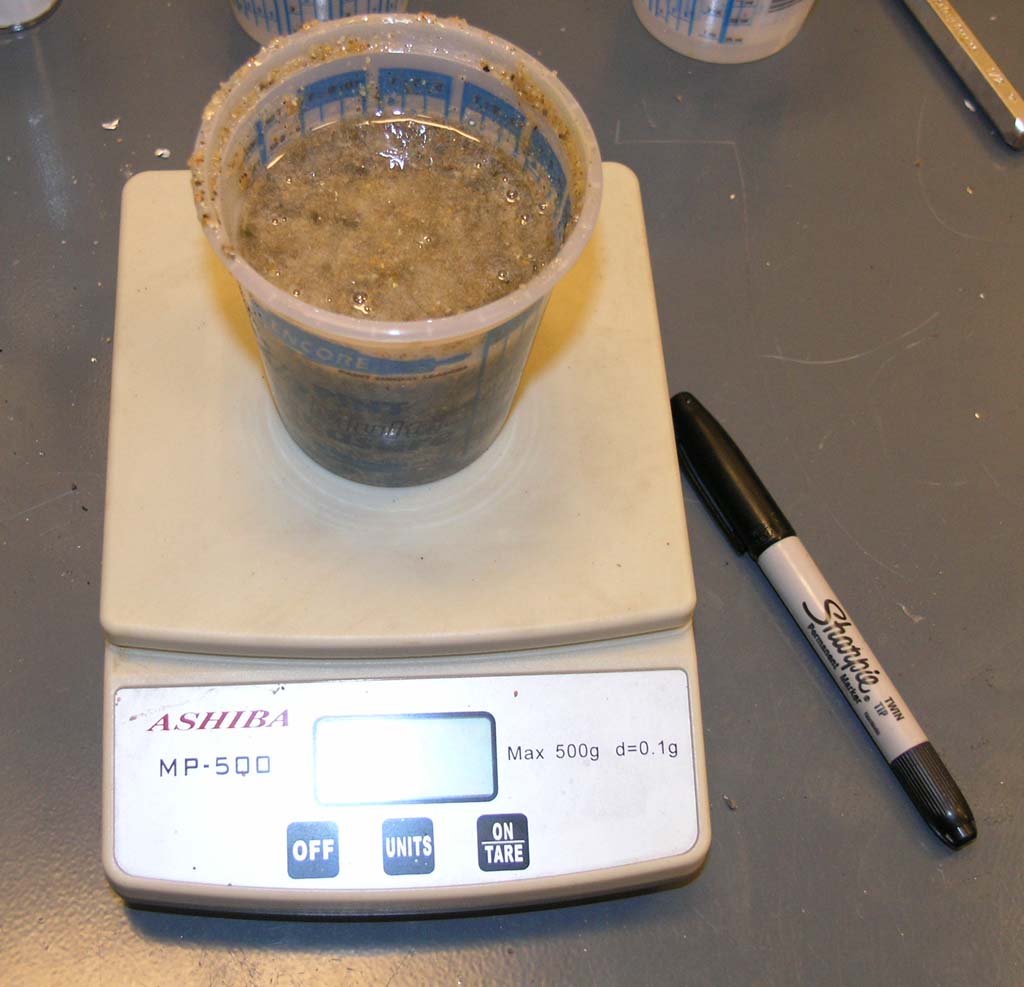
The test subject...
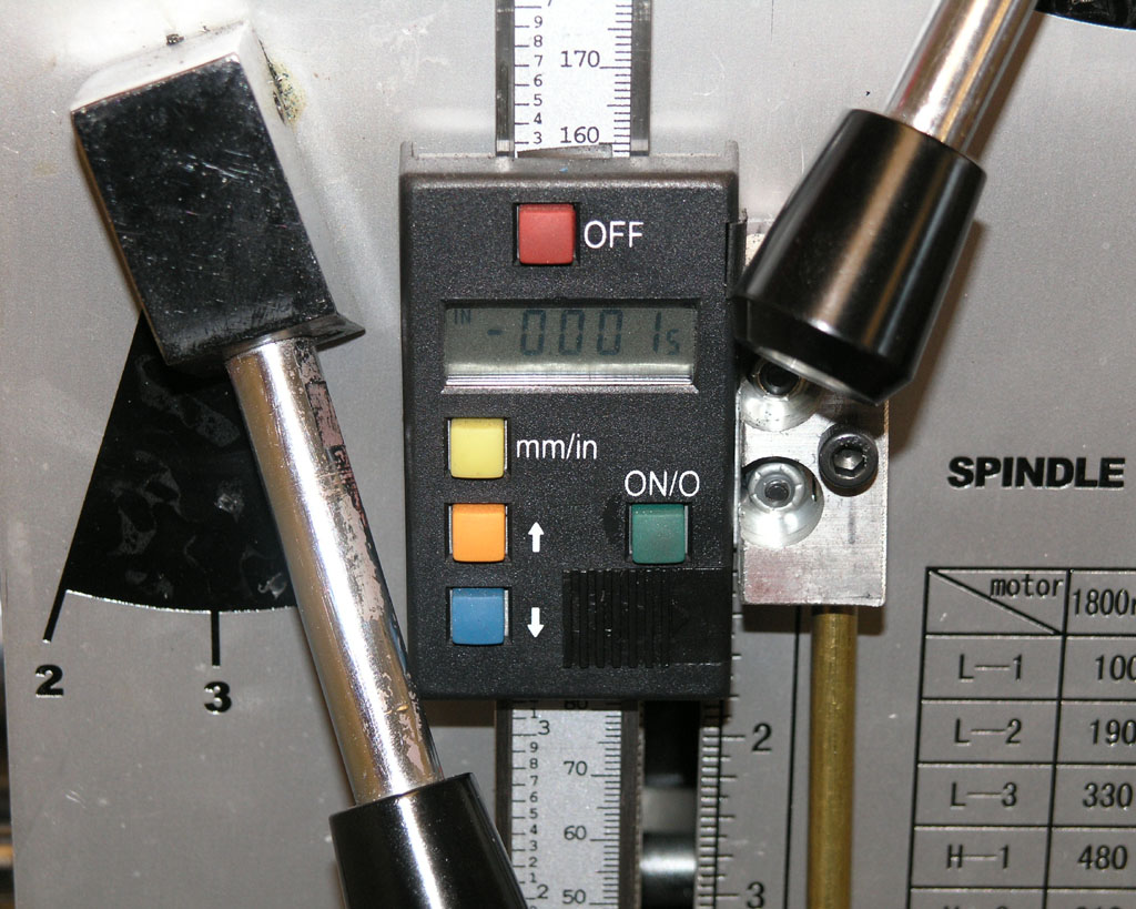
Calibrated Tailstock
Most people don't think about this, but your tailstock has a screw with a fixed thread so that it moves a fixed amount for a given rotation. One can take advantage of this for fine positioning of the ram on drilling operations, and indeed some lathes come with a dial to let you read what's going on. Here's a dial that Evan, over on the HSM boards, made for his Southbend tailstock:
On the other hand, nothing quite like a tailstock DRO either:
It's interesting to note that none of this is necessary or useful on a CNC lathe. There, you'll put your drill bit in the same place as any other tool because the CNC can line it up on the centerline very easily. Actually, it's fairly easy to do even without CNC, and many say it makes for a more accurate hole. On a CNC, the tailstock is stricly used to support and add rigidity.
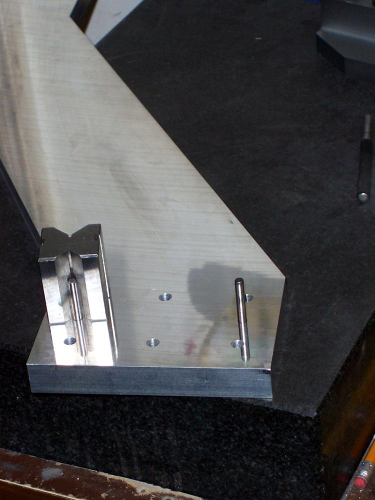
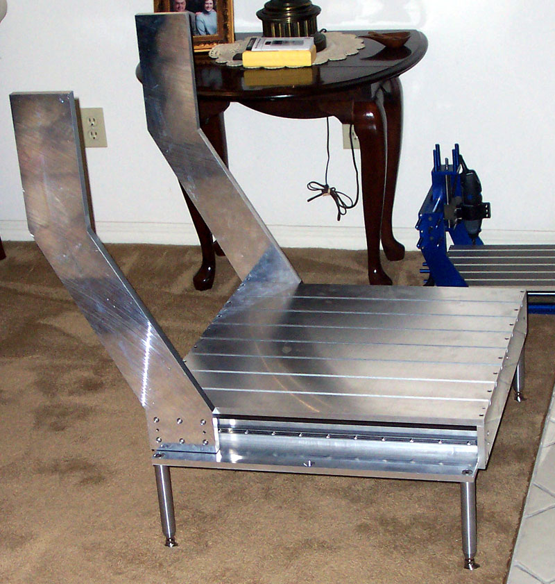
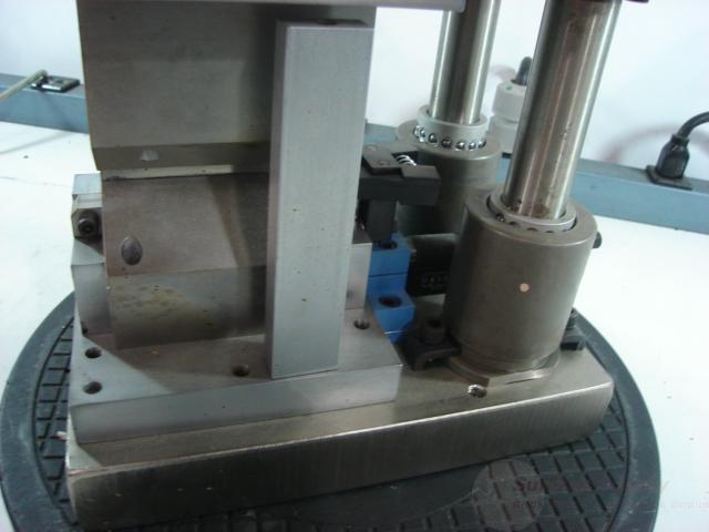
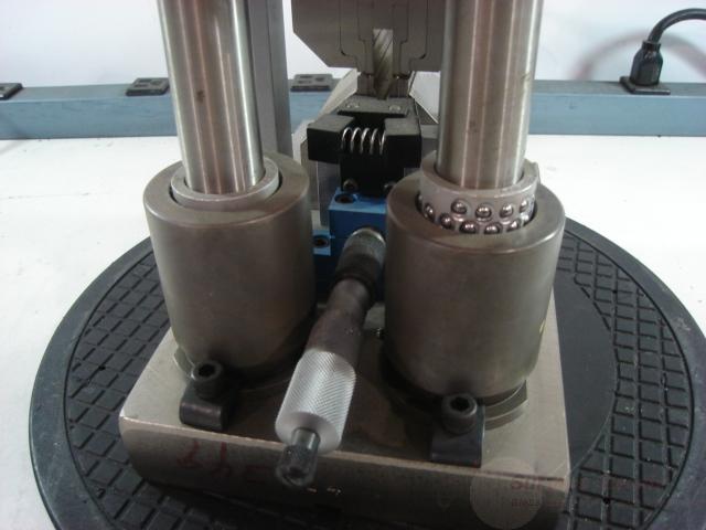
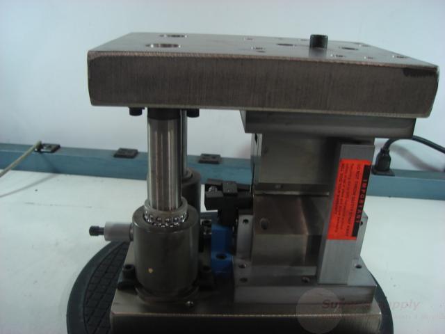
Killer Tilting Angle Table
Saw this gorgeous beauty over on the HSM board just now:
That's how tooling ought to be made, as opposed to how it all too often comes from the cheaper suppliers. That table is solid, and allows for greater angles than the import tables do.
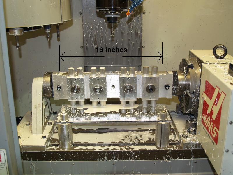
Looking at how beefy this table is made me think of a 4th axis with tombstone arrangement, like this:
Imagine an arrangement like that with your rotary table and you'd have the ultimate tilting table arrangement. I'd build the heck out of the tombstone, with a flange that is the diameter of the rotab's surface and holes to fit a T-bolt on every slot the rotab has. I'd even consider building a hollow tombstone whose center was filled with Epoxy Granite as a cheaper approach than buying such a big slab of cast iron. That's make a real nice project. The other thing to think about is what sort of tailstock features might contribute to rigidity. A pretty normal tailstock is shown here, but something more like this is beefier:
A purpose built tailstock that was seriously beefy and had a rotating flange with a hollow MT-compatible bore to allow standard lathe-style live centers would be neat. Put some kind of monster tapered roller bearing or bushing arrangement to stop the flange rotating when desired, or just use a dead center and let the flange rotate so long as it has no play and is solid.
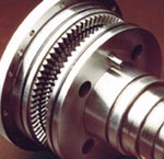
When I get ready to build a 4th axis, I'll be thinking along these lines, probably with the whole assembly mounted on a tooling plate for easy swap in and out. FYI, I bid on and got a 50:1 reduction Bayside Harmonic Drive, which will be an ideal basis to build a 4th axis around. Much better than a rotab--no backlash. I'm also going to want to install some way of locking the axis during cutting, probably using a compressed air powered clamp or perhaps a system like the pros use involving meshing bevel "face gear" teeth:
Keep the teeth apart and you're unlocked, bring the teeth together and the axis is locked. One set of teeth are keyed to the shaft, the other are rigidly mounted to the chassis.
3/1/08
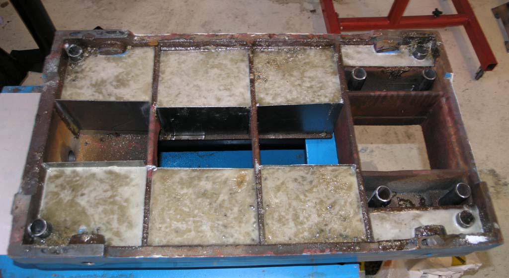
One Shot Oiling System Grooves Complete; Epoxy Granite Fill Beginning
I've now finished grooving the ways on my IH mill for the one shot oiling system. Here are the ways you haven't seen yet:
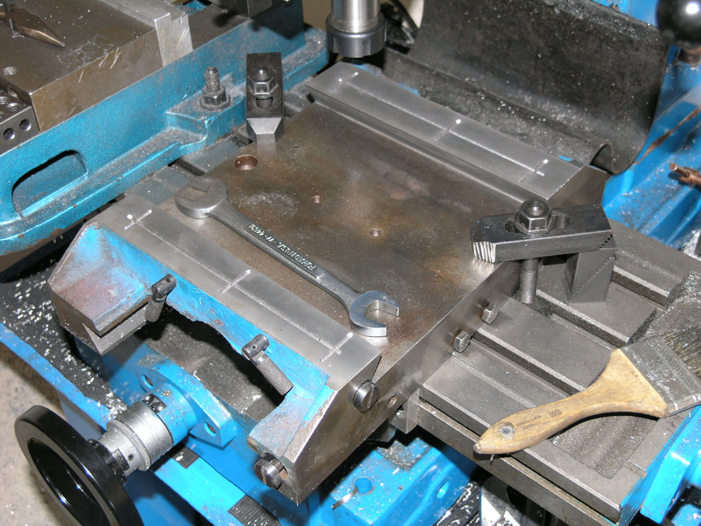
Y-Axis grooves...
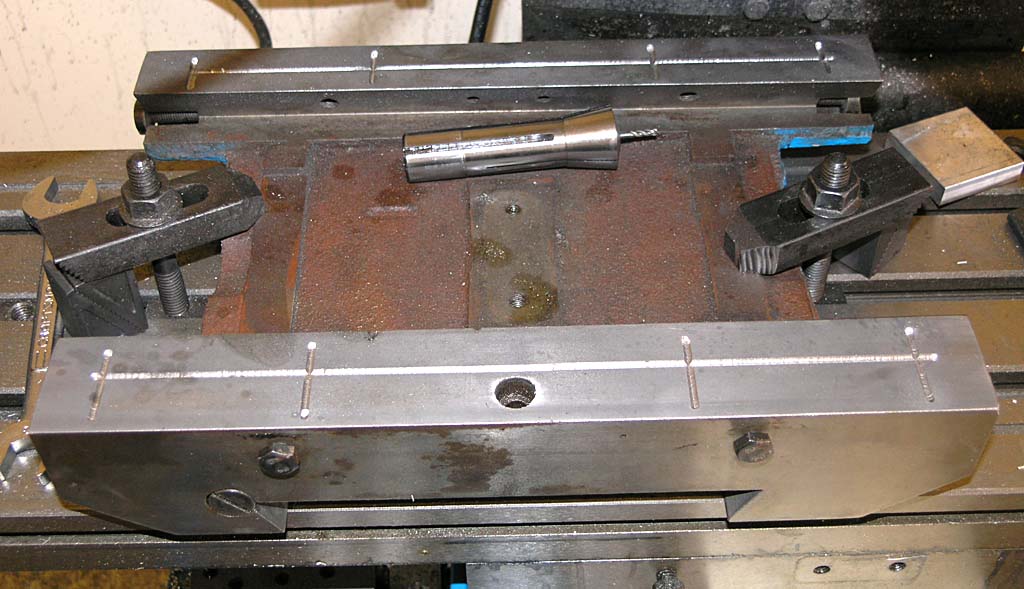
X-axis grooves...
Work has begun to do an Epoxy Granite fill on the base in order to increase dynamic stiffness:
Containment system is sheet metal and tubing. It'll keep the epoxy from going where it's not wanted. I basically want to fill the outer cells and keep the inner section and the vertical bolt holes clear...
Bijur Mist Coolant System
I've now ordered 2 of these Bijur systems:
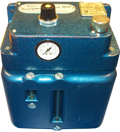
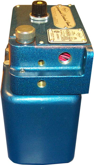
They seem like a deal for $80 from eBay seller govnuk. Bijur no longer manufactures them. These are New Old Stock, so eventually govnuk will run out. What you get is just the coolant tank. It has a 1 gallon capacity, site gas, pressure regulator, and solenoid valve. The seller includes an instruction sheet with it, and says he has nozzle assemblies, but those aren't listed on eBay. I plan to make my own mister nozzle, see my project wish list page, they aren't hard.
To get one of these working you'll need to put together a nozzle, plumb it to the tank, provide air to the tank, and provide electrical to the solenoid valve that triggers the coolant. The valve is ideal for a CNC system because its easy to use a relay to control your coolant. For a manual machinist, you'll want to rig a switch probably alongside your spindle controls.
These units are real nicely made, so if you're looking for this kind of thing, it could be a good buy!
You'll have to connect air
2/27/08
Build a Rack for your Air Tools
A little piece of angle bracket and a 5/16" end mill to cut a bunch of slots and you can create a handy rack for air tools:
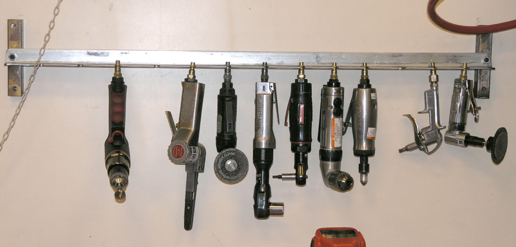
Got more of 'em than I thought!
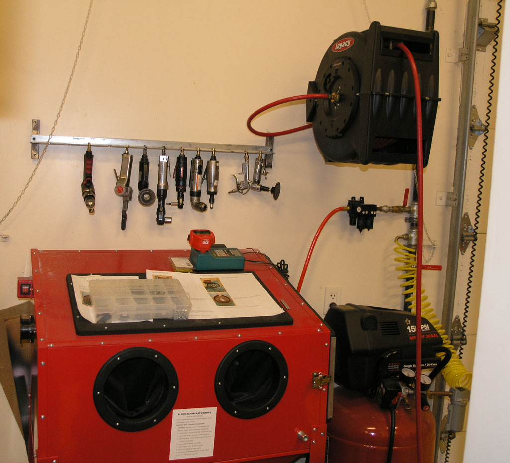
Grab the tool you need, connect to the hose and go!
2/24/08
Big News from Gecko: G540
Gecko has both a new low end stepper drive and a fascinating new 4-axis "motherboard" setup that sound like they'll make it simpler and cheaper than ever to get a CNC project done. Here are a few specs on the G540, which is the more interesting to me:
540 contains 4 heatsinked G250s short-circuit, motor disconnect, over/under
voltage, reversed polarity, thermal protect. 4 DB9 motor cable connectors
DB25 parallel port connector ported for Mach3 12 position 5mm removable
terminal block misc I/O and power Power and Fault indicator LEDs anodized
aluminum enclosure internal socketed fuse 2.4" by 5.7" panel mount cut-out
needed, 1" deep (61mm by 145mm by 26mm) 1.5" by 6" 4 mounting screw
pattern, up to #6 screw size (38mm by 152mm) The pricing is the major
selling point with these drives: The G250 will be selling for around
$35 each, and the G540 will be selling for under $300 (Prices are yet
to be finalized until the first 1000 are run and we have a good idea
about what exactly is involved).
So, for circa $300 you get 4 drives and a parallel breakout interface all ready to go on their own little chassis:
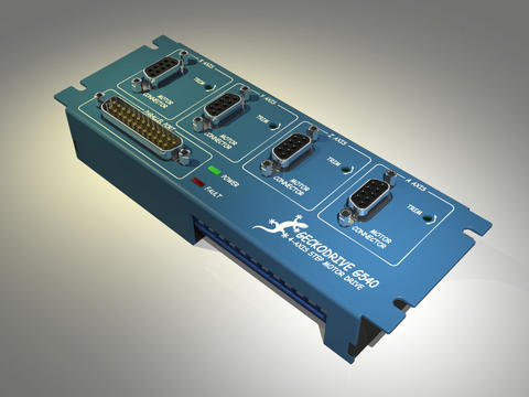
Awesome value!
Started Collecting Information on Press Brake Attachments
There's a new page where I'm collecting information to eventually build a press brake attachment for my hydraulic press.
2/23/08
Started the One Shot Oiling Mods
I cut the oil distribution grooves in the Z-axis and tried it out. Works good! Full details on the One Shot Oiling page.
IH Z-Axis Modification Completed
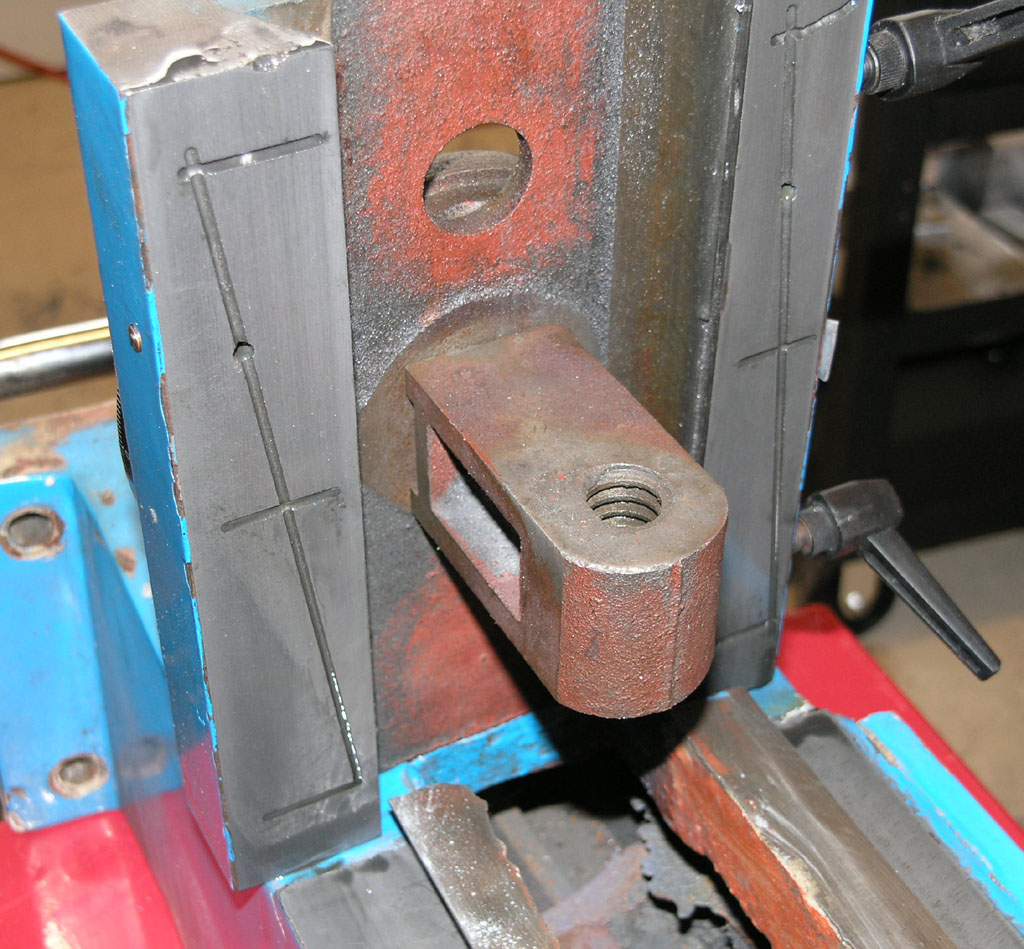
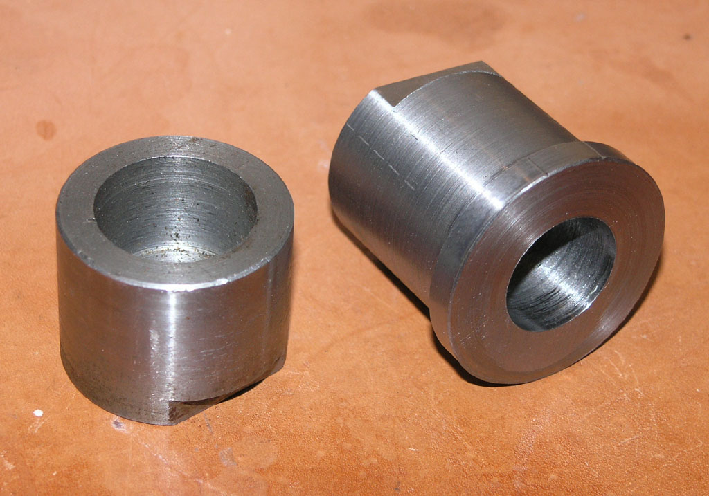
Just finished making a new bushing to rigidly attach the leadscrew nut bracket for the Z-axis on the IH mill to the Z-axis saddle. This is a source of play in RF-45 mills that's easy to eliminate, and one of the mods I wanted to get in before converting the mill to CNC. Here are the two bushings, with the original on the left and my new and improved on the right:
More details on the mill CNC conversion log.
Hardinge CHNC Lathe Restoration
I've been following this great thread by Vince over on CNCZone as he restores this Hardinge lathe. What a beast!
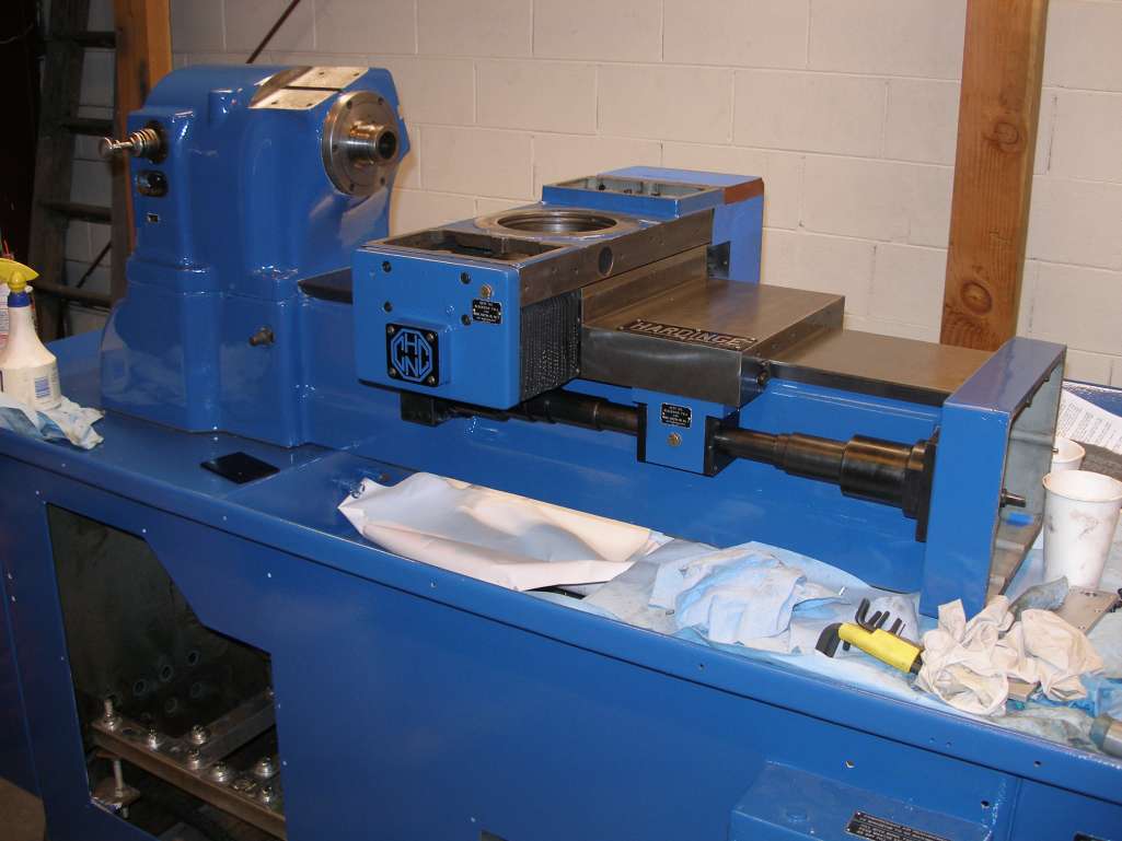
Classic Hardinge lines are under there somewhere, but the turret and cross slide are massive!
Most of the work so far has just been a matter of cleaning, painting, and adjusting.
2/22/08
More Widgitmastering
I get a lot of value from watching the antics of the Fidgiting Wigitmaster. He's a regular over on CNCZone and a superb machinist. He's busy cranking out a new and improved CNC router design, and has started even a newer design than that one. I have one of his first smaller machines, and it is a masterpiece of craftsmanship. One of the great things about Widgitmaster is his photo essays where he shows every detail of what he is building. I always learn a lot looking at these essays and often grab a few of the photos to pass along here:
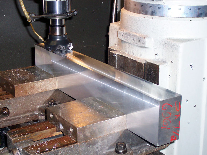
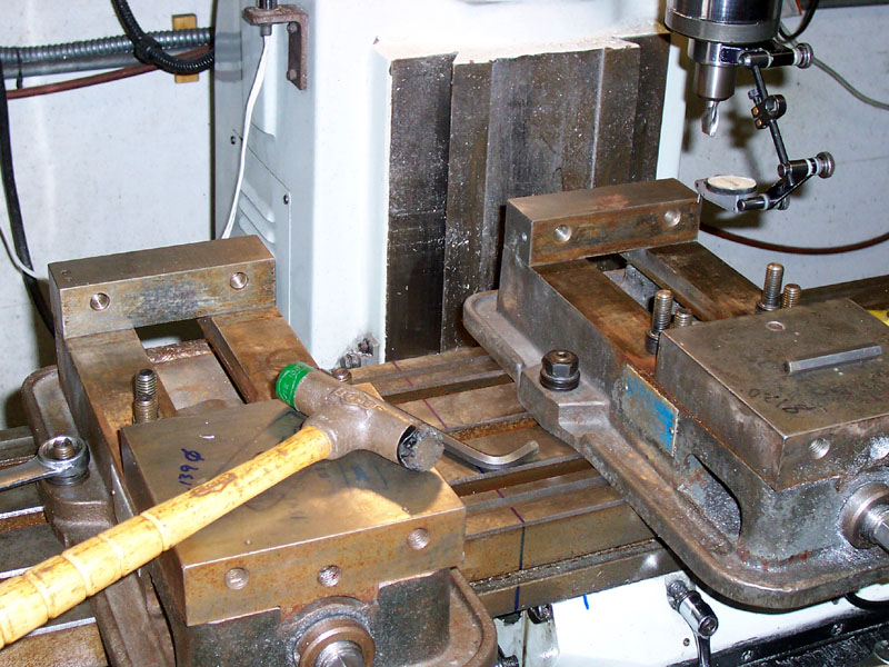
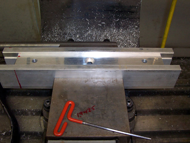
With two vises you can really support this big chunk o' aluminum...
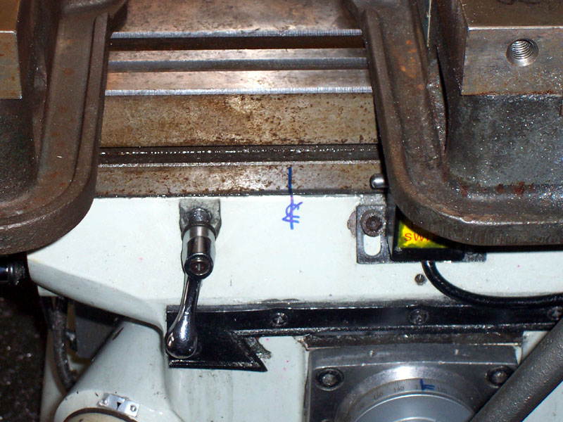
The mill table's centerline is marked with a Sharpie. Seems handy to know that point. He's also dialing in the jaws on these vises so they're both properly aligned to the table's travel...
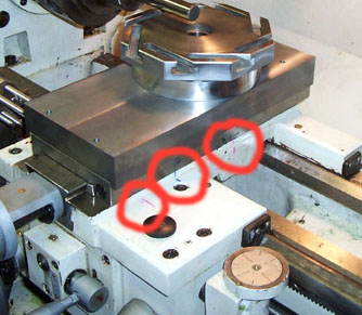
And the lathe slides travel limits are also marked...
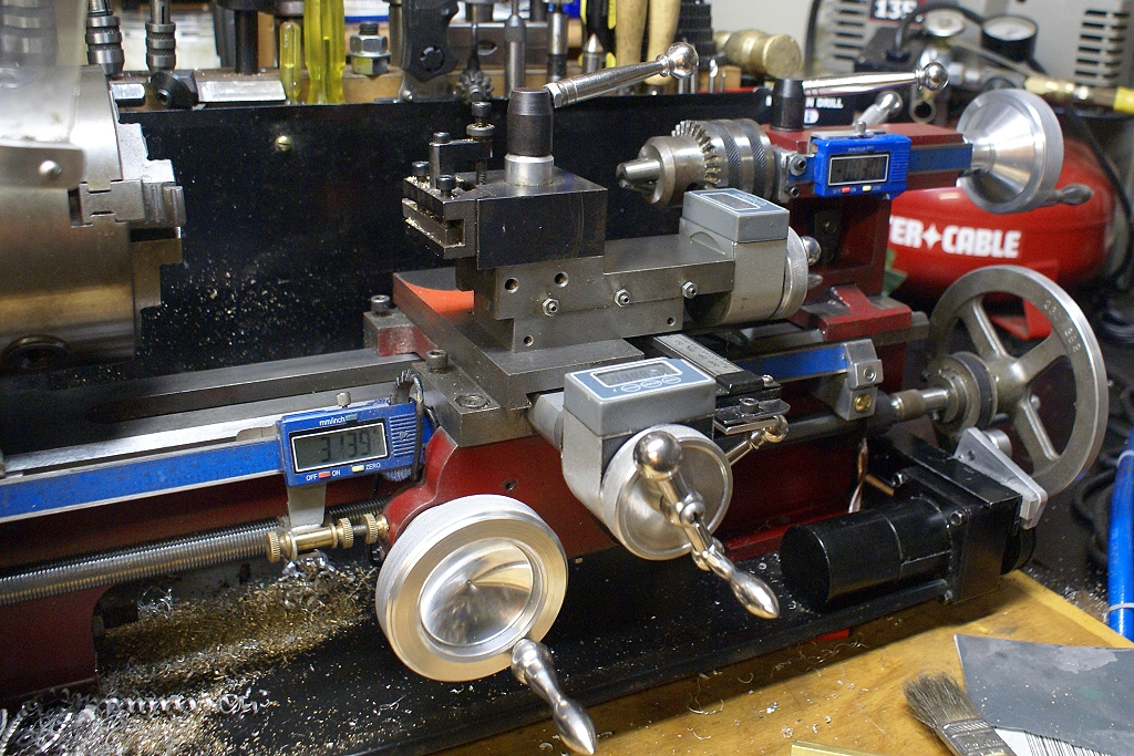
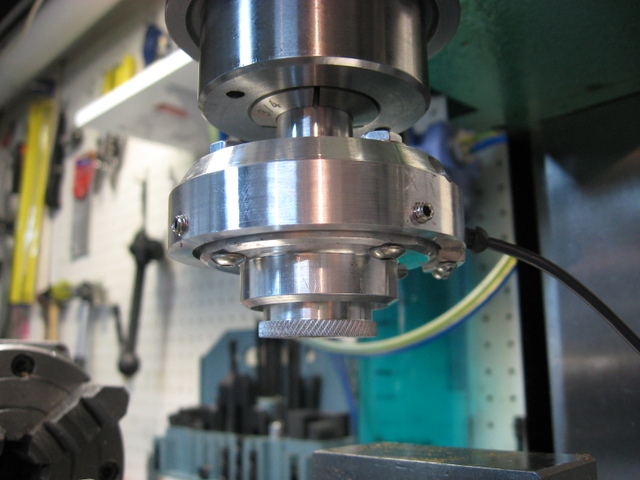
Got A New Toy: Coaxial Indicator
I got a knock-off of the Blake Coaxial Indicator from Shars and got a chance to try it out today. Man, what a cool gadget!
Here it is in action as I center the spindle over that hole so I can use my boring head to make a shoulder on the hole:
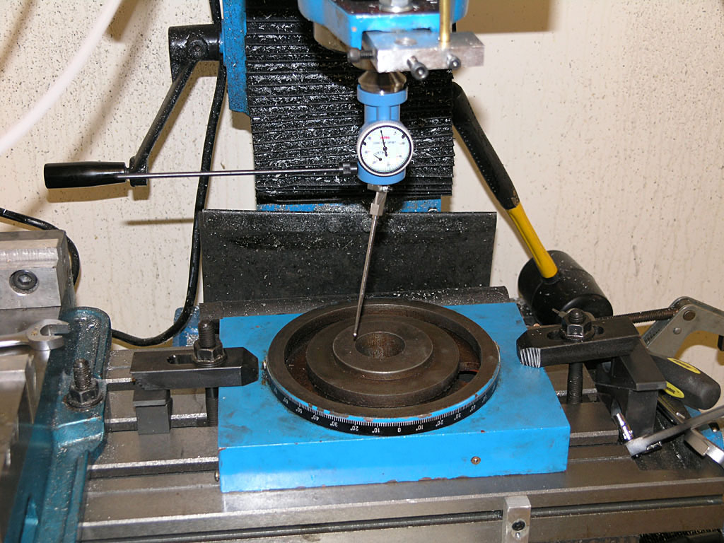
Picture that long feeler as being sort of like a very exagerated finger from a dial test indicator. It goes against the inside of the hole, or there are curved feelers for the outside of a round boss. You turn on the spindle at the lowest rpm, say 100rpm, and hold the horizontal rod. This keeps the indicator facing your way while the feeler sweeps around the circumference of the feature you want to center on. As the feeler sweeps around, the needle will "kick" because the spindle axis is not centered. Now adjust the X and Y axis handwheels until the needle kicks as little as possible. That's all there is to it, you are done very quickly. What a nice gadget!
Adjust the axes one at a time and don't even think much about what's needed. Simply turn the wheel and observe whether the needle kicks more or less. Turn it in the direction that kicks less. When you've minimized the kick on one axis, do the other. I circle back a second time around and got to almost no kick at all.
I did not set up the Indicol and DTI to check the result as I was in a hurry, but visually, after I used the boring head to make the shoulder, it looked spot on.
It tool longer to stick the Blake in the R8 collet than it did to adjust the X and Y axes, or so it seemed. Apparently they can also be used to dial in a 4-jaw chuck. I'm going to love having this little gadget around I think!
2/20/08
An Elegant Widget is On The Way
Watch this thread carefully!
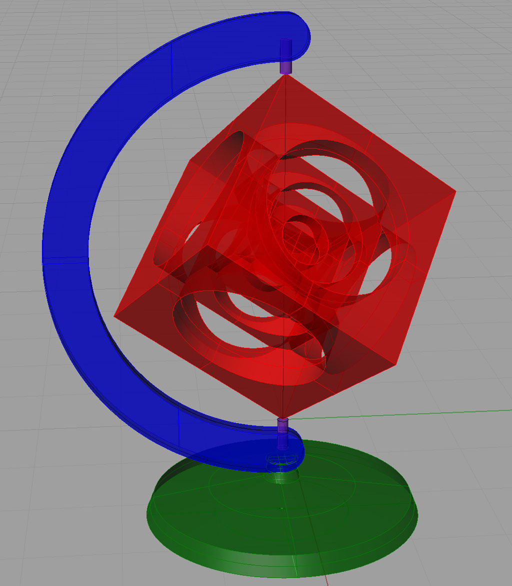
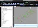
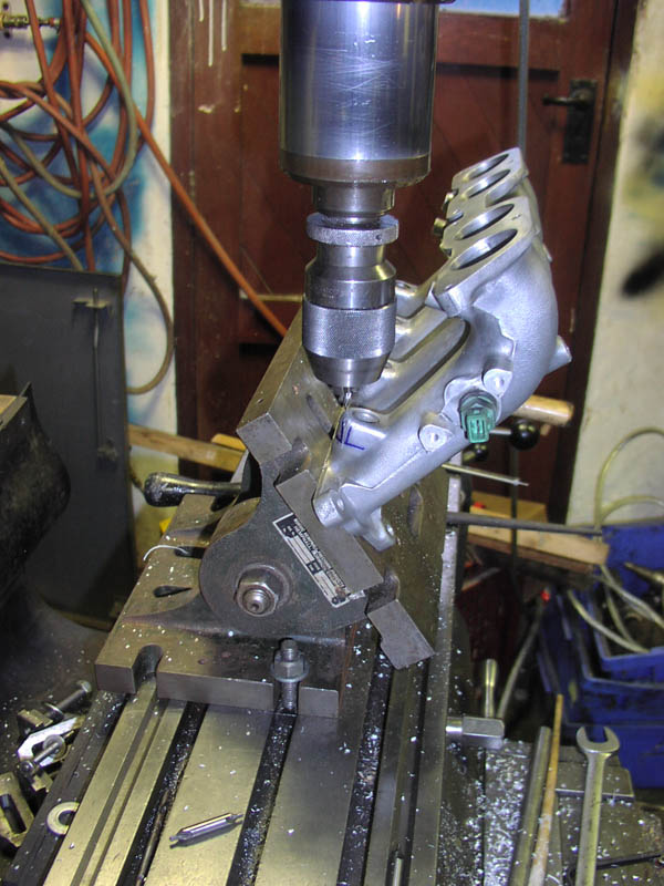
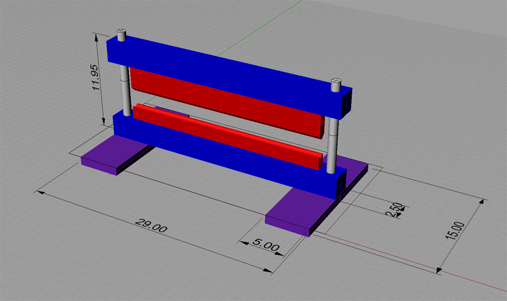
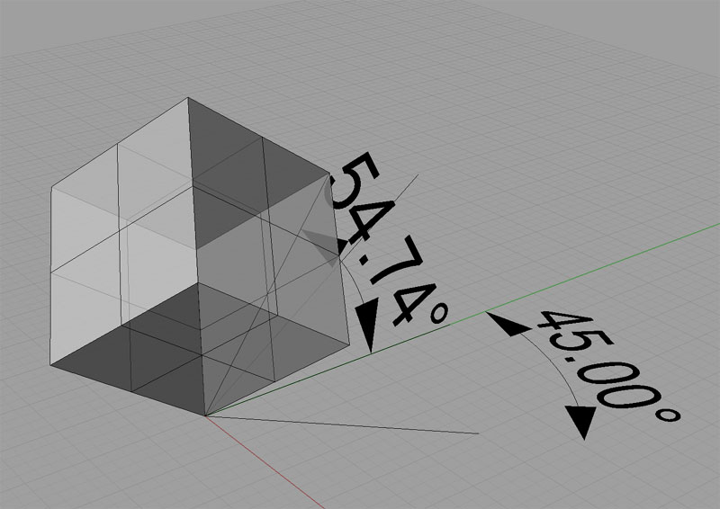
To put the cube on end requires two rotations, one around the Z (vertical) axis and one around the X-axis to tilt the cube up. The amount of the second rotation was not obvious without the CAD program to help figure it out:
Add a Little Positive Rake to Your Parting Tool and a Chip Catcher to Your Chop Saw
I found a neat new site the other day called The Alchemist. This fellow has a 3-in-1 and has done a lot with it. One of his articles I liked involved grinding a little rake into his parting blade so it looks like this:
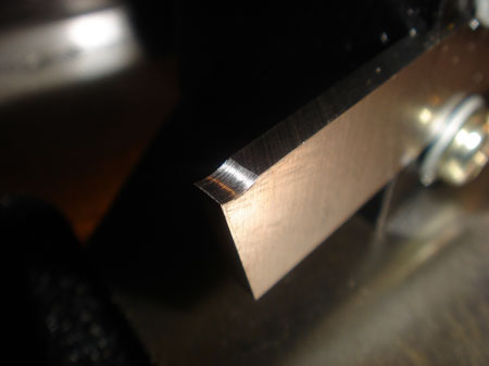
Just a little bit of work put this positive rake end on a parting blade...
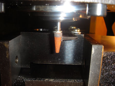
The grinding was accomplished by sticking a Dremel abrasive point in a collet and workwith the parting blade on its side in the mill vise...
According to the author, the combination of this modification together with more aggressive feeding greatly improved his parting performance. It certainly looks easy enough to try, so I'll have a go one of these days!
I also liked his special table for his chop saw (a DeWalt Multicutter like mine) with a "chip catcher" attached to his ShopVac. I could use more ShopVac automation to keep the flying chips under better control, and the DeWalt throws out a torrent of them.
Here's the chip catcher and stand:
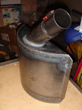
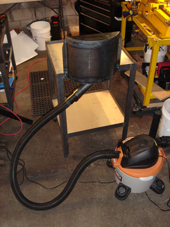
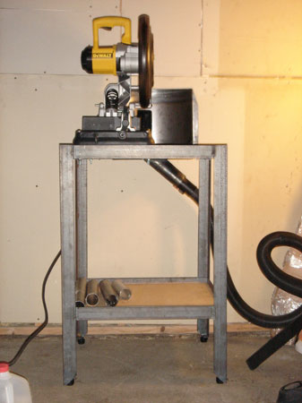
Go check this guy's site out, it's cool!
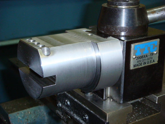
Wedge vs Piston Quick Change Toolposts for the Lathe
In case you ever wondered what the difference is, here is my piston style Phase II QCTP:
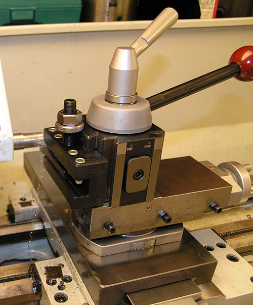
The rounded edged rectangular thing in the middle of the dovetail is the piston...
The rounded edged rectangular thing in the middle of the dovetails is the piston. When you turn the red handle, a cam action pushes the piston out which forces the tool holder against the dovetails.
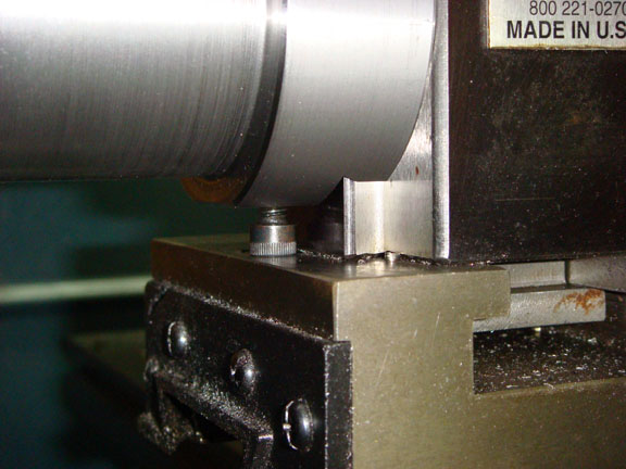
Now here is a wedge style QCTP:
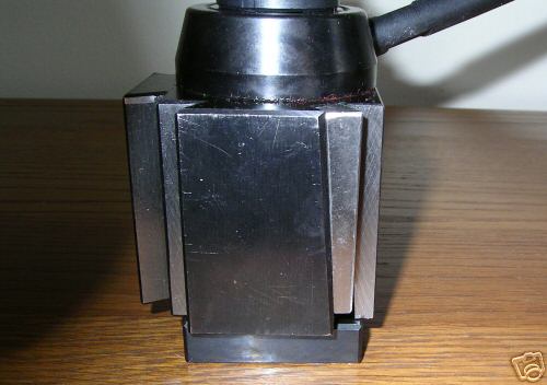
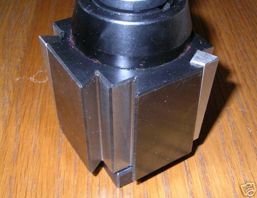
Wedge style has sort of a tapered gib that moves down...
There's no piston. Instead, there is a wedge-shaped gib that moves down to lock the QCTP holder securely in place. Presumably the machined tolerances are a little different to in that there is likely no slop to change the distance from the axis of the QCTP to the end of the tool. This is the motion the piston causes by pushing in that direction. The issue with repeatability would be that it means your dials on the lathe don't mean the same thing when you change tools. The wedge seems to me will also force the holder downward against its height adjustment screw.
You can also see why the wedge-type cost more--they look more complex to make. It's tempting to try to make one though, isn't it?
2/19/08
IH Mill Y-Axis Lapping Completed: Before and Afters
I finished lapping the Y-Axis this evening and consider the process a success. Here are some before and after pictures:
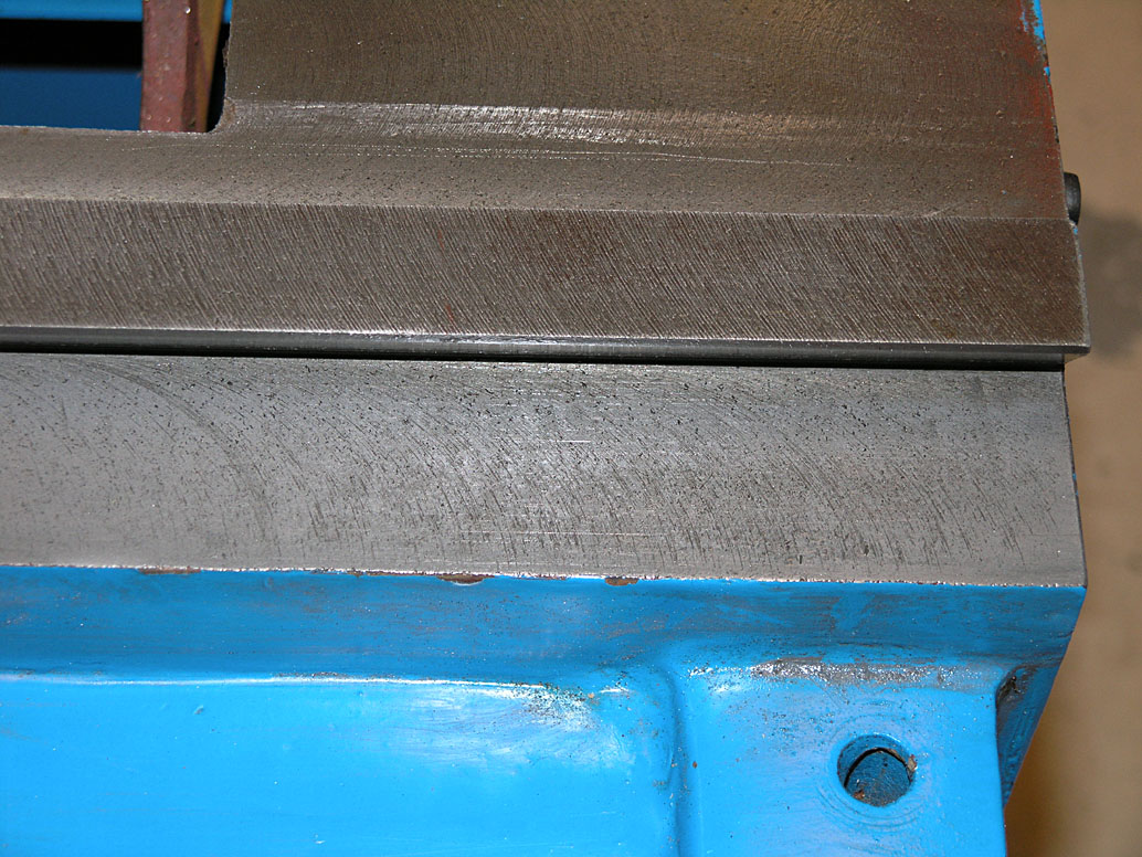
Before lapping: kinda gnarly with lots of heavy tool marks and porosity visible.
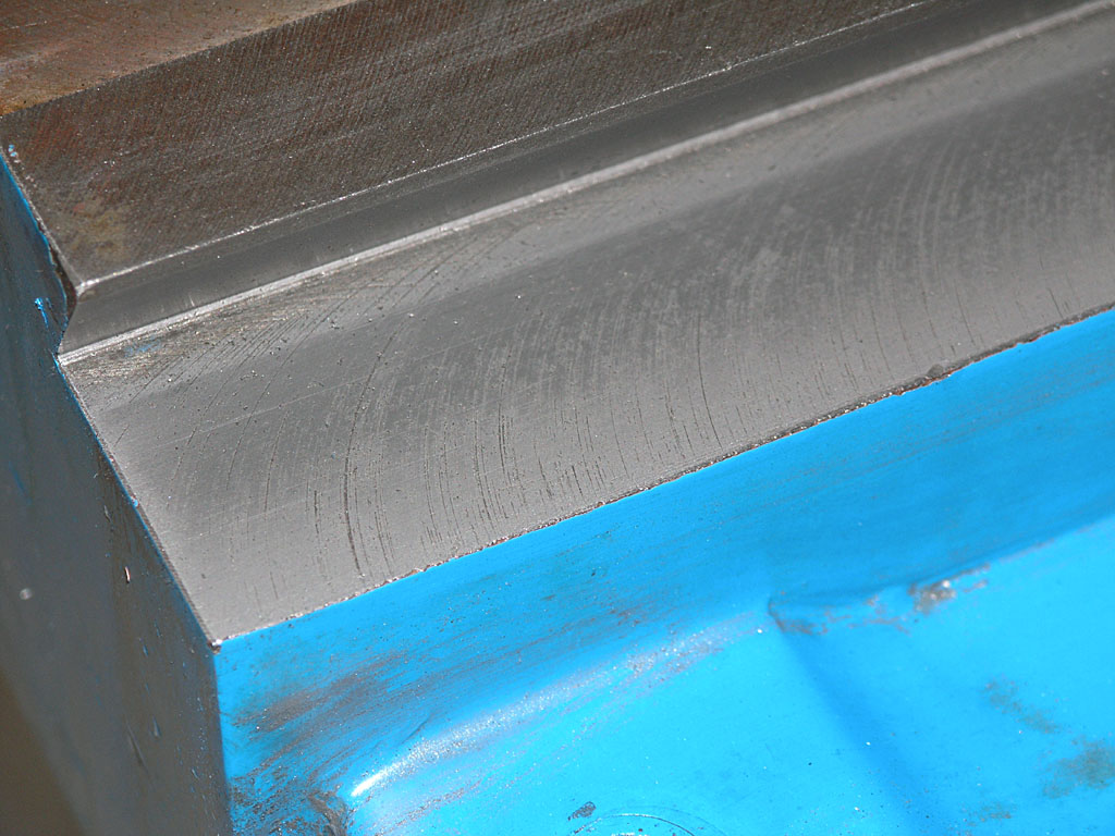
After lapping: note how much smoother things have become. There's even a bit of a reflection of the dovetail. We aren't trying to remove all the toolmarks, just to make things smoother so the gibs can be run tighter and we get less "stick-slip" friction.
All in all, the operation was a success in my mind. The surface is noticeably smoother to the eye, but more importantly, you can really feel a difference moving the saddle along the ways by hand. This can be done smoothly even with gibs tighted. I'm skeptical how well that would have worked before lapping with nothing but kerosene as a lubricant.
2/17/08
Conversion of My IH Mill to CNC Has Begun!
The process of conversion began today. My second IH mill has been sitting on the shelf for a little over one year, and I decided to finally get going on the conversion work. Fortunately, the mill was disassembled before being put away for storage. Equally fortunately, I applied a treatment of Break-Free rust inhibitor to all the bare metal surfaces, so there was no rust to speak of visible anywhere.
To make it easy to follow the conversion, I'll be writing a blog on the home page of the CNC conversion. Separate sub-pages will be created for special projects such as the one shot oiling system I'm planning to add. There is an awful lot that needs doing, so I'm trying to track and organize it all on a ToDo page as well.
The first step to complete is lapping the ways. This is a controversial procedure, so check the conversion log for my explanation of why I'm going ahead with it.
I don't expect to complete the CNC conversion straight through--it's a long haul. I will likely be taking some "breather" projects in between, but I'll post to the conversion log whenever I make progress, and if it's particularly newsworthy, I will post here too.
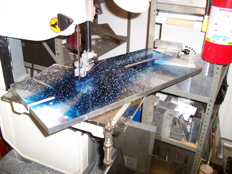
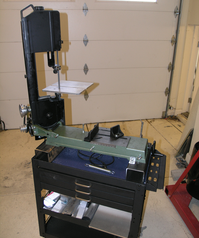
Restoring the Usefulness of My Mini-Bandsaw With a New Table
I made a quick afternoon's work making a new table for my mini-bandsaw and mounting it on a cart I use to keep small pieces of work stock:
First Time With a Drill Doctor
Various people complain about the Drill Doctor not working, but people I respect feel that's a matter of not properly following the directions. So, when they went on sale at Amazon for half price ($99 for a DD7500), I bought one. It sat for a couple of days until I was having trouble with an overused bit that had dulled. Out came the Drill Doctor. I will admit the instructions involve a number of steps, but it isn't that hard to follow them to the letter. It took me 10 minutes the first time I ever used it to unpack it, figure it out, sharpen a bit, and take these pictures:
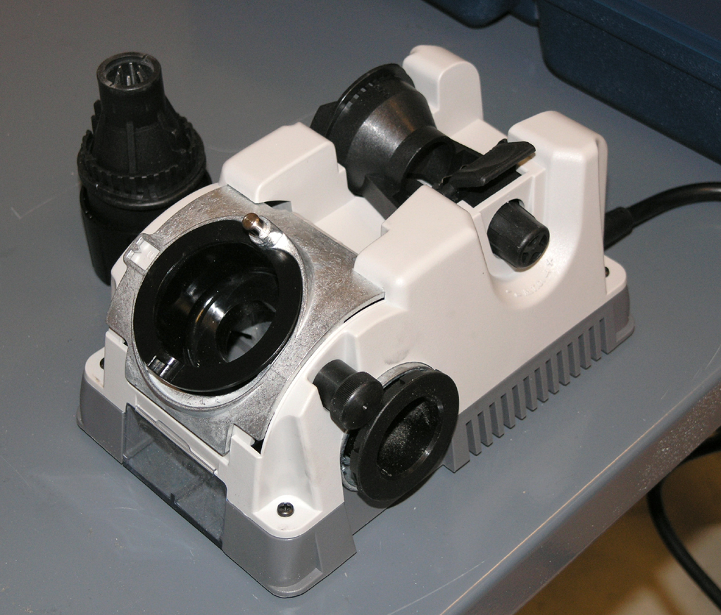
The Doctor is In!
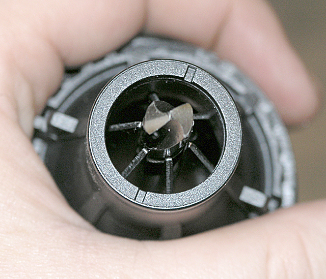
Before and after. The bit on the right is freshly sharpened to 118 degrees and split pointed. I should've kept after the split point a little longer: I could've brought the two sides a little closer together, but even so, the bit cut WAAYYYYY better after that little treatment.
Drill Doctor is recommended by CNCCookbook!
On the Business of Deburring
Most machining operations leave little burrs and sharp edges. You want to remove these, first so you don't cut yourself or others, and second because its just a bit of craftsmanship that ought to go into what you are doing. There are a lot of ways to deburr as well as tools to make it easier. Here is my array of deburring equipment:
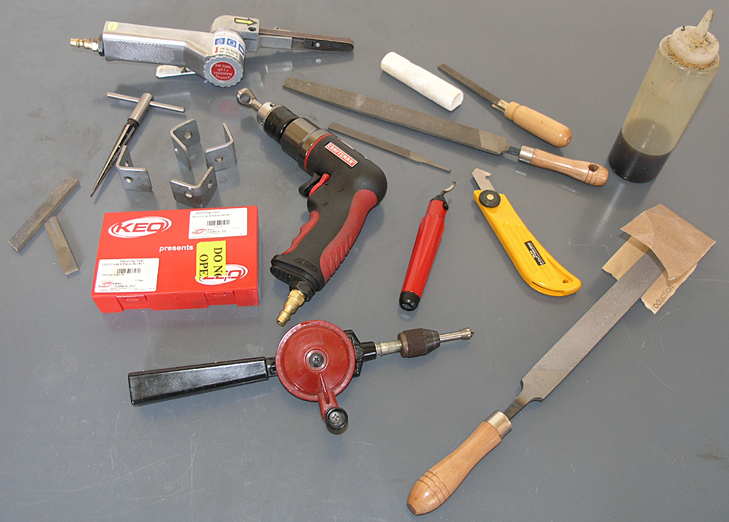
Let's go left to right, top to bottom:
Always remember to be especially careful deburring things that are spinning, such as on the lathe. You don't want to get caught up in that or serious injury can result!
When all else fails, I have my super deburring tool that I just made, my 12" Disc Sander:
Cool Little Pratt & Whitney Instrument Maker's Lathe
This is one cool little older lathe I saw on eBay. The price was almost $1500, so I didn't bid, but I thought it was a neat machine:
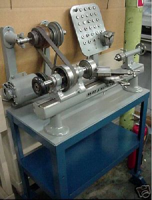
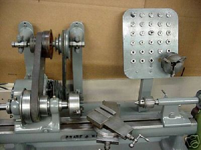
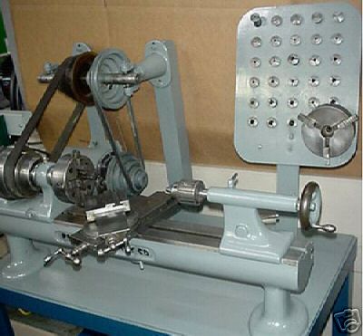
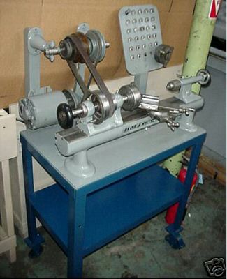
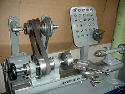
This little guy supposedly weighs 300 lbs, has a 7" swing over the bed and 16" between centers. It certainly looks pretty beefy for the size work it would be used for. The lathes web site identifies this as a Pratt & Whitney No. 3 Precision Bench Lathe.
2/16/08
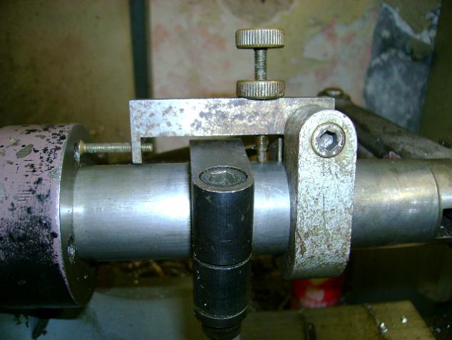
Work Stop Ideas for the Lathe
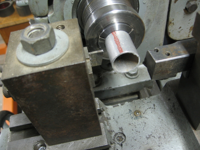
This started as a question on the PM boards about how to create a stop so a set of parts cut be parted off to the same length +/- 0.010", which is a pretty coarse tolerance. Several respondents had some neat tooling for the task:
An additional end stop goes into the T-slots alongside the compound. Crank the stop into position, run the bar up to it, lock chuck or collet, start lathe and crank the parting off tool.
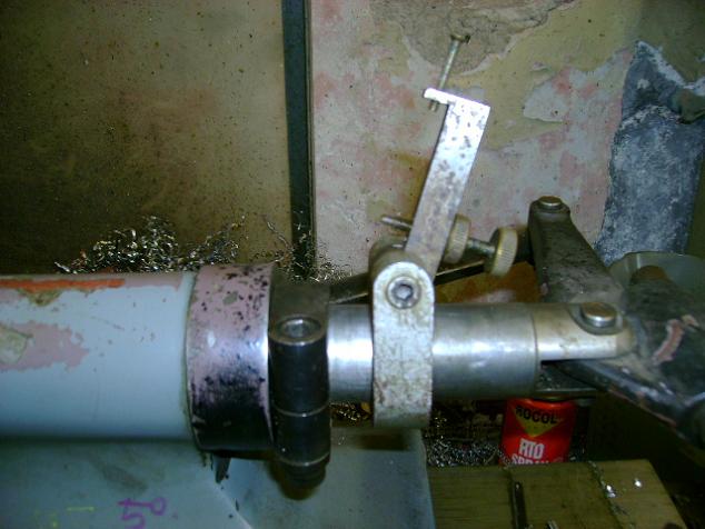
Leave the tailstock loose and crank for rapid drilling with the end stop working against the chuck and tailstock ram...
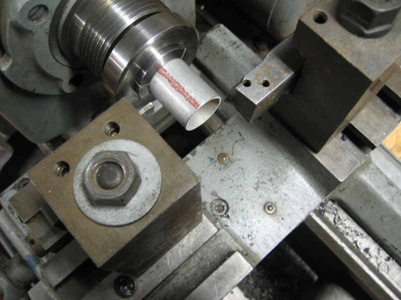
Part off tool in front, facing tool upside down on rear tool mount. You can use the facing tool also as a stop. So, move workpiece against stop, face it, part it off, and repeat. This is manual gang tooling...
This Hardinge lever operated tailstock has a stop to set the motion...
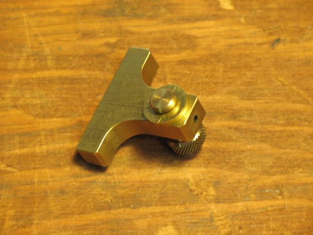
Some Marv Klotz Inventions
Marv has a neat collection of software for machinists and is a frequent HSM and HMEM contributor. I keep a link to his software page on my reference data page because it is so handy. Marv is also a consumate toolmaker, so I thought I'd pass along a few of his many handy gadgets here.
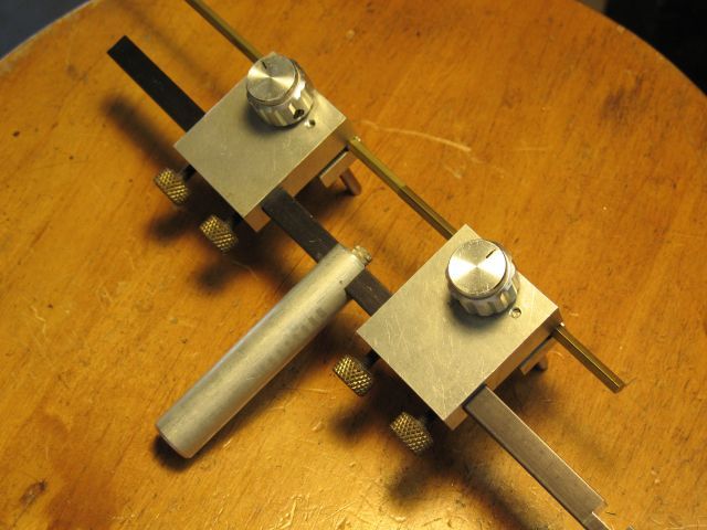
Gosh that looks handy, doesn't it? A little more precise than the usual alligator clip "3rd hand"!
The Rod is 3/8" square. They cylinder fits a Panavise base. Marv says he's torn about making the vises of aluminum because they act as heat sinks, but at least they're less likely to mar the parts...
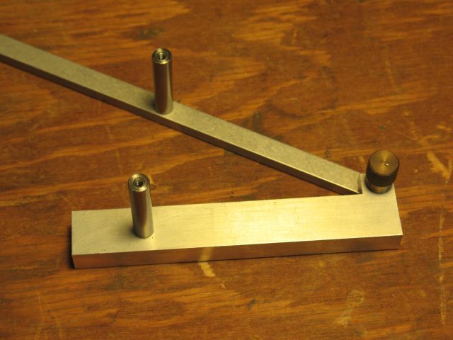
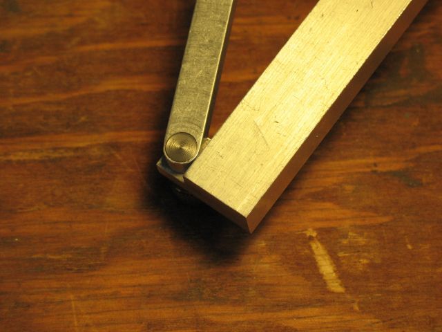
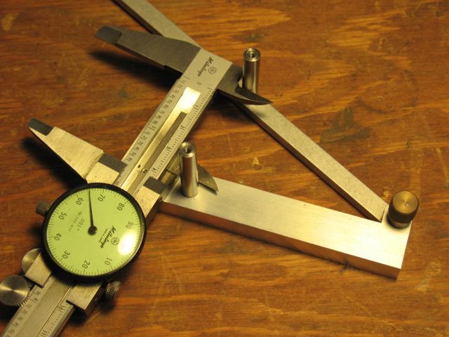
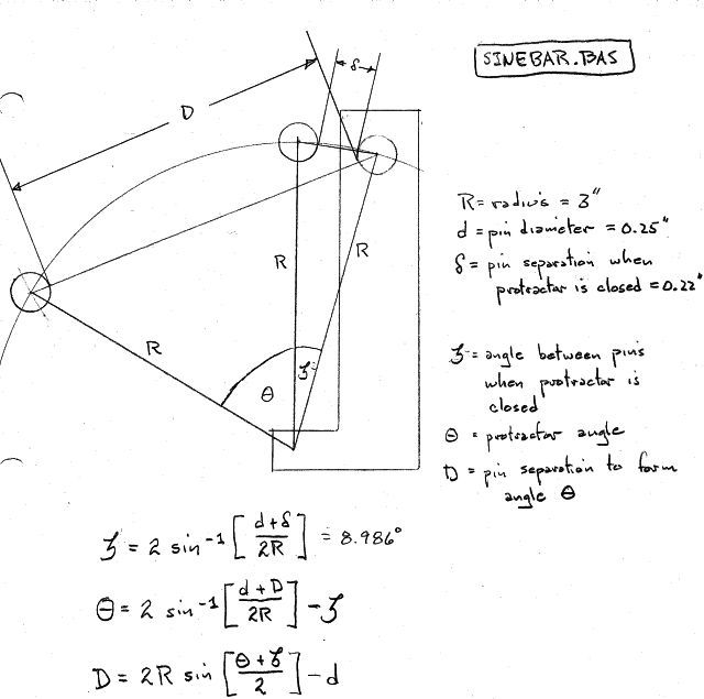
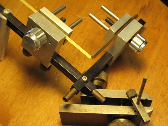
The protractor can get into tight spaces and accurately measure angles using the sine bar method.
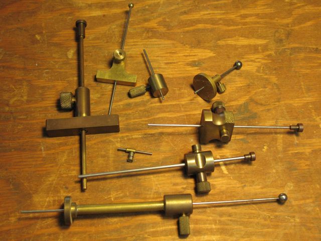
An amazing array of depth measuring instruments to reach into all kinds of difficult places both large and small...
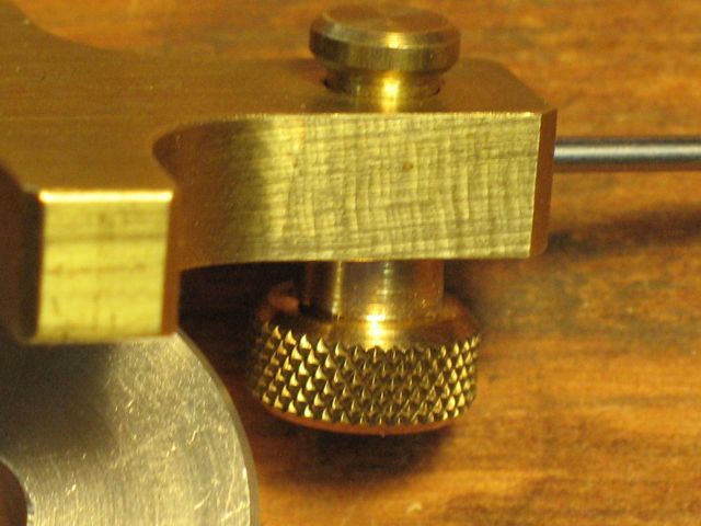
The idea here is that the washer holds the collar out while machining the depth rod hole. Now we have a gage where you "press the button" to hold the measurement until you get clear and can operate the thumbscew for a final lock.
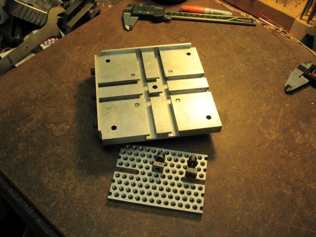
Milling plate has T-slots, tooling plate, clamping system, and a trued square block to go in the milling vise.
Here is a small part affixed. Do we see the beginnings of a VMC palette changer for a Sherline sized CNC?
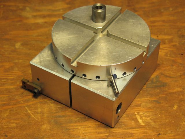
Tiny Indexing Table for the Mill
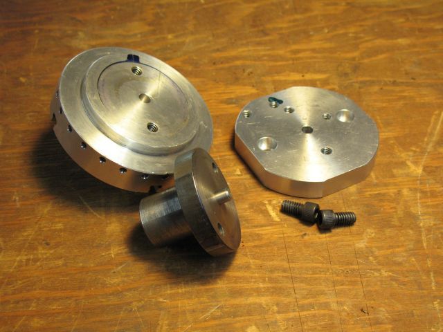
The spigot is interchangeable and used with other tooling...
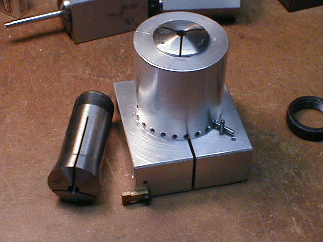
As is the dividing fixture...
2/12/08
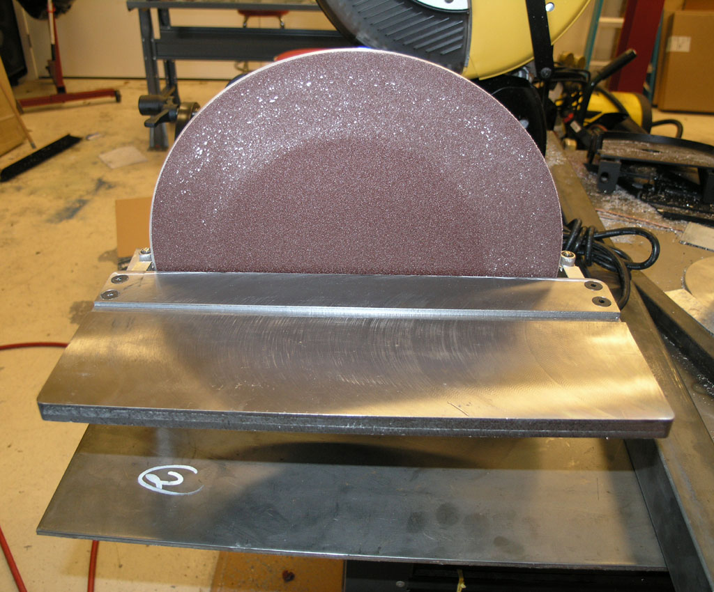
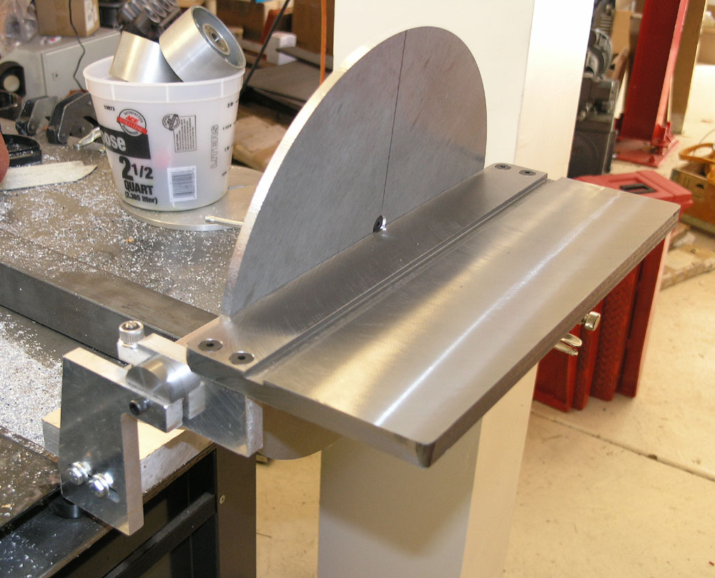
The Disc Sander is Done!
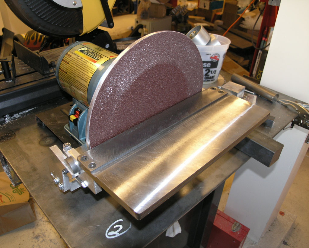
My new Thing of Beauty!
It's a powerful beast. I was pushing hard rounding an aluminum bracket and the 3/4 HP motor didn't even think of slowing down.
2/11/08
More Disc Sander Progress
I got the table assembly mocked up:
Starting to look like a disc sander, eh?
The blow by blow is in the disc sander project pages.
Mic Stands and Universal Vise from 800Watt
eBay seller 800Watt is perhaps infamous on the web. Some people have had problems, but I've always done well. I get what I ordered and its pretty much what I expected. I don't look for these Chinese tools be exceptional, just adequate. That's the end of the market they're aiming for, and consequently they're cheap. Just yesterday I got in a couple of items that were really very nice. I decided I would never get around to building micrometer stands, so I ordered 2 from 800Watt for $5 apiece. They're nice cast iron units with good feel:
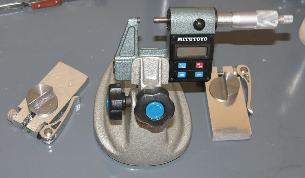
800Watt Micrometer Stand With My 0-1" Mitu...
My second item is something also from 800Watt that just seemed too cheap to be true. It's a Universal Vise for tool grinding that I paid $55. These are complicated beasts to make, although Mcgyver made a nice one. Name brands often seem to be big bucks too. I found the quality on this one to be excellent, so I'll probably try to set it up to sharpen cutters once I get a chance. Here's what it looks like out of the box:
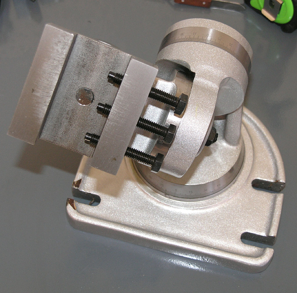
Nicely made, no?
I found an extra bonus in the box too. In order to make sure the vise would not be able to slide around, 800Watt threw in a couple of the "instant on" mini-Butane blow torches. Handy!
You can bet I left him nice feedback. That reminds me, is it my imagination, or have eBay sellers suddenly gotten a lot nicer? In the last week or two I've had two of them refund part of my shipping, I got the extra torches from 800Watt, and there's something else that caught my eye but escapes me at the moment.
2/09/08
Tramming the Mill More Quickly With Your Quill DRO
Tram is the squareness of your mill head to the table. There is tram parallel to the x-axis, and tram parallel to the y-axis (sometimes called "nod"). Depending on your machine, you may have a swivel head that is designed to cut at angles other than square for more flexibility. For machines with adjustable heads, you need to check the tram fairly often and rest it.
I try to check the tram on my mill whenever I begin a new project. That's really not often enough. Most machinists I've talked to check tram when they come in every morning, and quite a few will also check if someone else uses the machine during the day. The point is, if you need accurate cuts and the best finishes, your mill needs to be in tram.
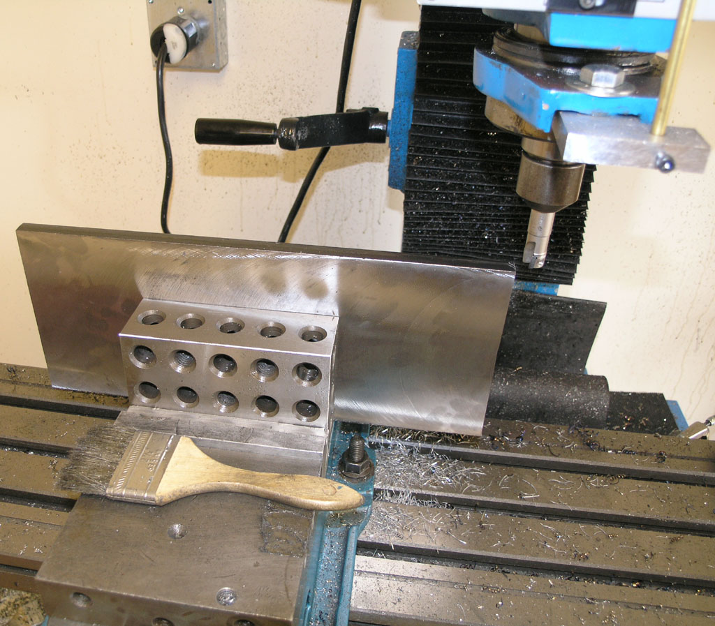
At some point, I developed a procedure that I find easier and faster. Here is my basic setup with the DTI on my Indicol and a couple of 1-2-3 blocks to provide clearance over the vise:
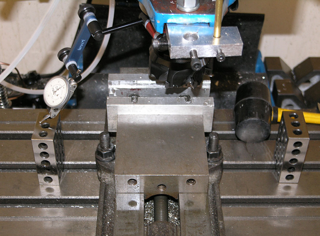
Basic tramming setup...
The goal is to have the DTI have the same reading on either side, indicating the spindle is square with respect to the table. The Indicol is not the best tramming setup, BTW. A proper tramming bar would be more rigid and less "jumpy". For example:
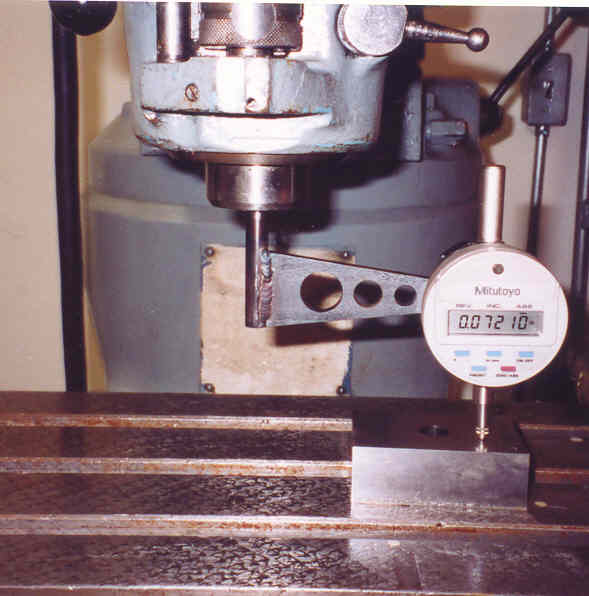
Here's a nice tramming bar that goes in a collet...
At some point, I decided to try using my quill DRO and the DTI like a sensitive height gage. I would raise the DTI off the 1-2-3 block on one side, lower the quill until I saw DTI motion, and press the zero on the quill DRO. Then I raise up off the block, flip it around to the other block, and lower down until the DTI registers. Now I can read on the quill DRO the difference between the two sides. Next I bump the head in until the Quill DRO/"Height Gage" reading is 1/2 what it started out. Repeat the procedure until you're within acceptible limits. I was able to get pretty close in 2 cycles of this:
Head is now trammed within 0.001" on about a 10-12" circle. That's pretty close!
Hardinge Ballscrew Coverst
Thanks to Vince on CNCZone who is restoring a Hardinge CHNC lathe for this shot of the ballscrew covers:
Dang they look solid, don't they?
2/07/08
SPI Gage Block Set
Enco has a ridiculous deal on SPI Gage Blocks right now: regular $484 on sale for $169. I'm a sucker for a bargain, and I've gotten some nice things from SPI in the past so I bit. I already had a mungy Chinese set that I got for $50 off eBay, but this promised to be a little nicer. I wasn't disappointed!
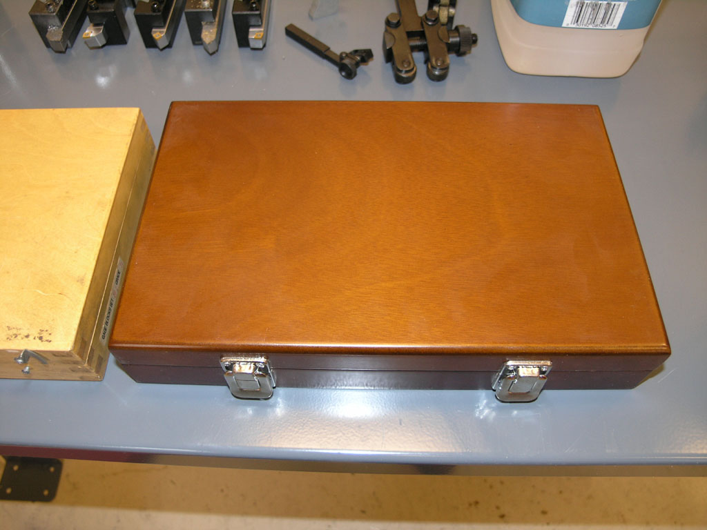
The case alone is gorgeous compared to the normal wooden cases from China...
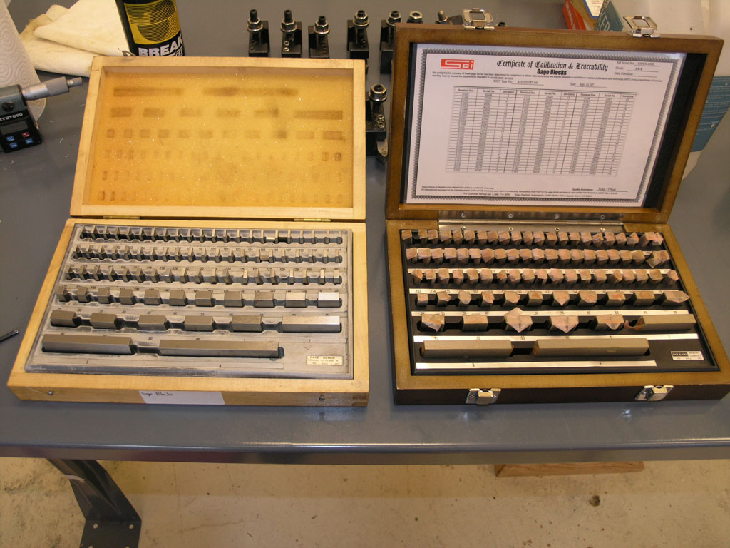
Here are the two sets...
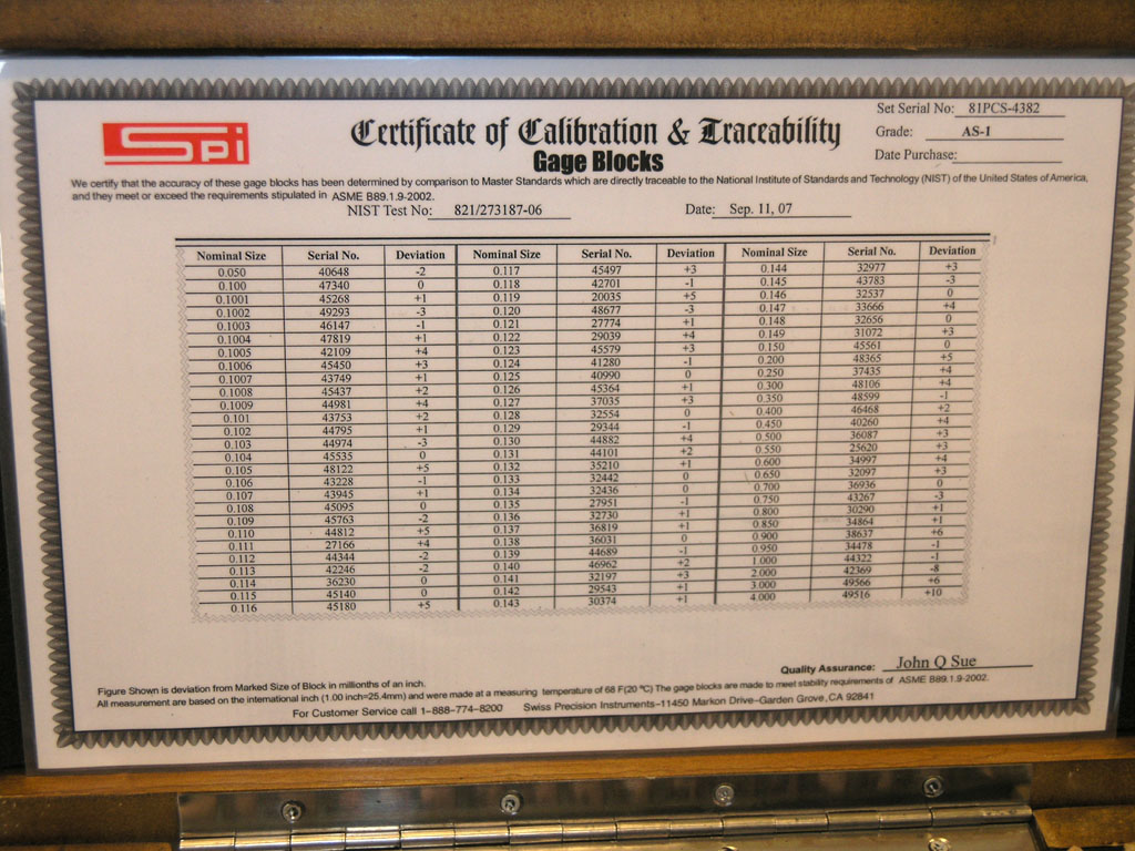
The certificate of traceability with a NIST traceable test certificate is the winning indicator of quality on this set...
QCTP Lathe Tooling
I got 5 new QCTP holders in that I ordered from CDCO. They were $10 apiece, so they were irresistable. I went ahead and stuck some tools in them so they'd be ready to go, and decided I would photograph my collection of lathe cutters for my QCTP:
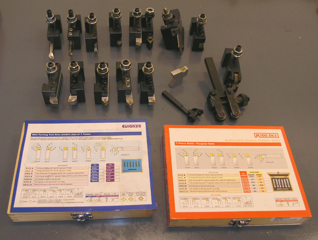
Most of it originates from the two sets in from. One is a 3/8" CCMT set from Glanze, the other is a Micro100 set with 1/2" shanks. Clearly they're the same stuff just looking at packaging. The 1/2" shanks are a whale of a lot stiffer though, so I seldom use the 3/8" tools anymore.

Back row, left to right: 3 boring bars. The big and little ones are really nice Circle Boring bars. The middle is a very indifferent brazed carbide bar that came in a set. Next up is the plastigage. I like this tool because you can face and turn without messing with the tool, but my CCMT insert tools leave a better finish, so I don't use it very often. Next is my attempt at making 5Bears HSS "secret weapon" for fine turning. It has tons of rake and is kept sharp with a hone. I need to work on it more because I don't get as good a result as I think I should. Next is an Aloris tool with built in inserts. I liked the idea well, but the inserts have not been good performers. Are you getting to understand the insert really matters? I want to try and see if a TCMT would fit it, but otherwise I've quit using it. Last two on the back row are my big Aloris parting off tool and a little HSS cutoff blade I buy from an eBay guy. Both are great tools.
Front row shows the Micro100 CCMT tooling with 1/2" shanks. Then there's my nifty center height setting tool. I got it from Brownell's and it works really well! In front of that is an indicator holder I sometimes put into a QCTP holder so I can use an indicator on the lathe. And lastly, we have my knurlers. The scissor-type I got for $29.95 from Lathemaster. Haven't had a chance to try it because it won't fit in my QCTP's. I need to modify a QCTP on the mill to hold the big shank. The other is the standard knurler that comes with the QCTP set I got.
I still don't have all my tooling in QCTP holders, and there are some other holders I'd really love to have (like a drill chuck), so I guess I need to order some more from CDCO. Word on the boards is they're out of stock though.
Don't let anyone tell you carbide insert tooling won't work with small lathes. It's just about all I ever use!
2/04/08
GOLmatic Mill
Neat looking small CNC mill from the UK:
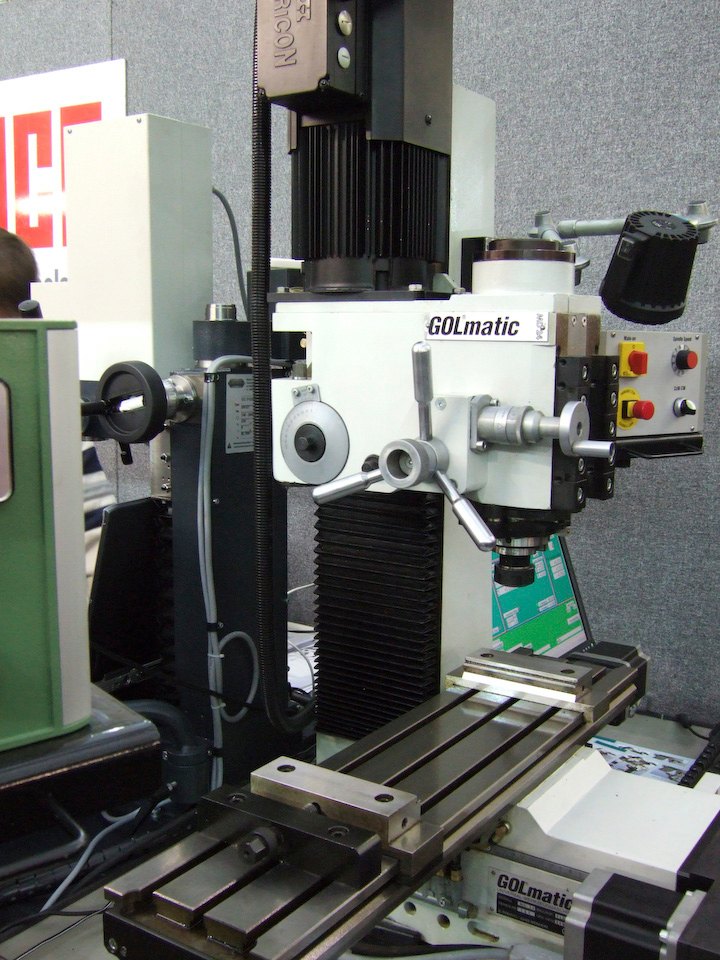
Interesting vise-like arrangement there on the table. I kinda like the swing arm light, but seems like it's in the wrong place?
2/04/08
Ultimate High End Workstations and Cabinets
Just discovered a line called "Beta" from Procare. This is high end stuff used by Formula 1 racing teams, and similar to Lista cabinets. Very cool looking garage furniture:
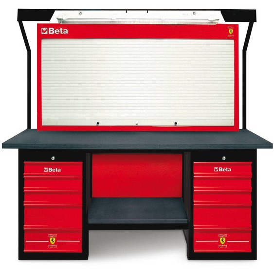
Scuderia Ferrari ring a bell? This work station is circa $6,000. Any Google guys who like shop furniture?

From the "Tank" series. I love this muscular looking station. Circa $2,300, but what a beast!
I don't want to spend so much on cabinetry, but I find myself wondering about building something like the Tank out of a couple cheaper tool cabinets with a new rolling base and counter top.
Lasers + Video: Multimedia Machine Tool Experience!
I recently came across two articles that had some absolutely fabulous ideas that are suitable for combining or could be used alone. First up was a CNCZone thread about a dirt cheap laser cross hairs (less than $5!). Real nice:
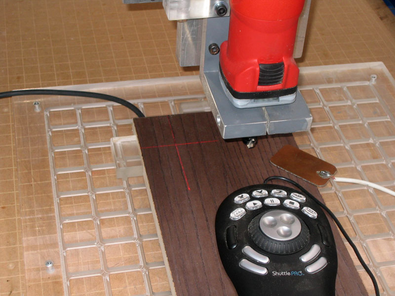
Laser cross hairs are offset from spindle axis because the laser is permanently mounted...
But wait, this gets more clever. He added some code to Mach 3 that deals with the fact the laser cross hairs are offset from the spindle. Here are the controls:

The target toggles the laser on and off. "Laser Zero" zeros the machine at the lasers current position allowing for its offset from the spindle! The X and Y DRO's let you enter the offset of the laser from spindle center.
Here is what the Mach 3 code looks like to do that:
Xmove = GetUserDRO(1152) 'X distance DRO
Ymove = GetUserDRO(1153) 'Y distance DRO
Code "G91 G0 X" &Xmove & "Y" &Ymove
While IsMoving ()
Wend
Code "G90 M9"
DoOEMButton (1008)
DoOEMButton (1009)
The M9 is to turn laser off after the zero. M7 turns it on. He's just using the mist coolant commands to run the laser. The two "DoOEMButton" zero the X and Y. The two DROs are to set the laser offset distance for the script.
But Wait, I Promised Video Too!
S_J_H over on HSM just published this Uber Cool housing for a $30 Logitech web cam:
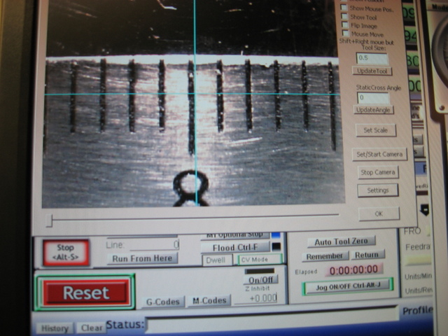
Mach 3 is all set up to display the web cam feed...
Put it all together...
My crazy idea is to combine these two. I want a permanent mounting bracket that holds a housing containing the web cam and integrated laser cross hairs alongside the spindle. We probably want a flip open lens protector as well. I also want it fully integrated so Mach 3 knows about the offset from the spindle. Now you have laser cross hairs when 0.1" is "close enough", and a 0.001" camera comparator for more precise work that is always there.
Wouldn't that rock? I think so. So cool I added it to my project list.
2/02/08
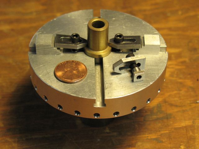
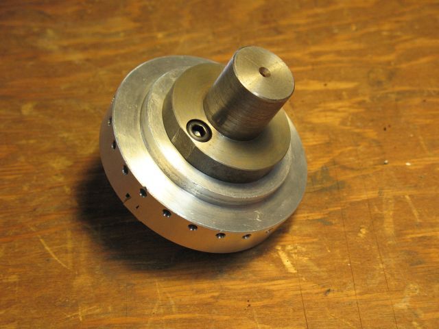
A Bit More Disc Sander Progress
Hub holes threaded, plate for disc drilled and countersunk, and some progress mounting a 4-jaw lathe chuck to my rotary table:
More info on the Disc Sander Page.
Kurt Vise Tricks
The versatility of the Kurt vise is amazing. With the right set of jaws, you can do almost anything. Someday I'll write a page of such tricks, but for now, a recent post on HMEM led me to collect these pictures and thoughts:
If your jaws are too narrow, try making extra wide jaws...
If the jaws aren't tall enough, try using 1-2-3 or 2-4-6 blocks to add some rigidity...
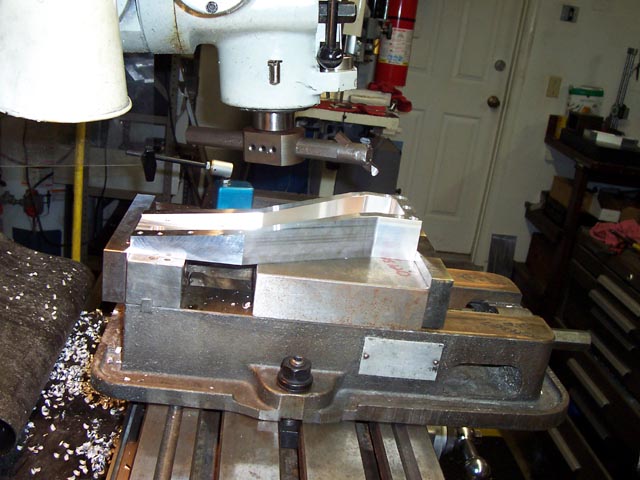
If the vise won't open far enough, mount the jaws on the outside rather than the inside, and you can't mount the vise on your table either way too...
A pair of Kurt vises in the same size becomes even more potent. For example, you can make a single set of jaws that spans 2 vises to hold really large parts. I've also seen sine jaws that have a movable piece for holding work at various angles.
2/01/08
Fridge Magnet Way Scrapers
I loved this idea from John over at the HMEM board to cut up rubber refrigerator magnets for use as way scrapers:
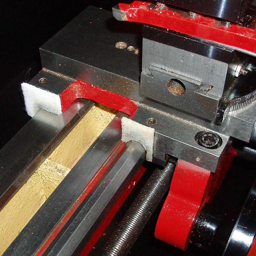
Rubber refrigerator magnets as way scrapers...
His thought to add a chip shield to the apron was also cool:
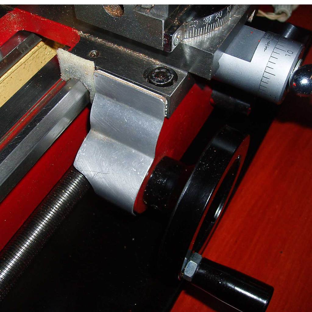
Chip shield protects the apron...
But it got me to thinking. I could use more protection on my lathe, but I'd like a shield not so much for the apron as the leadscrew. I think you could create a shelf-style shield that covers a lot of the area where the chips fly:
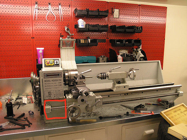
With the carriage all the way left, there's room for a shield the size of the red rectangle. That's the area most of the chips fall!
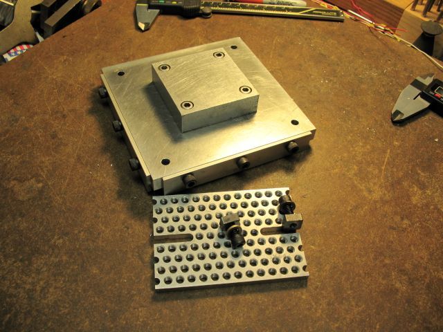
Mill Tooling Plate
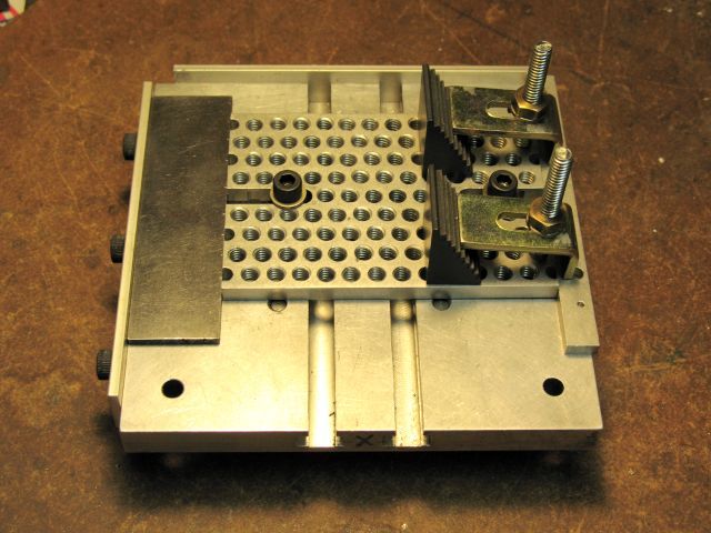
I like the idea of a tooling plate, so I perked up when S_J_H gave a couple photos of his nice plate:
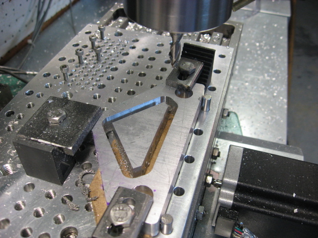
He's using a 0.25" end mill to cut out that shape. The stock is clamped to some sacrificial MDF, but there's also double sided tape, which keeps the piece from moving whe n the cut is completed. Note also the dowel pins aligning the work to the tooling plate. It's nice on a tooling plate to have both holes for dowel pins and bolts.
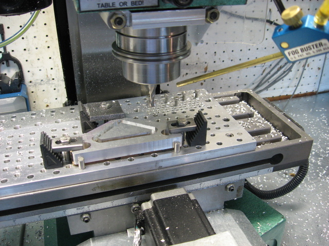
Another view of the tooling plate and also the fog buster used for cooling.
|
Do you want to be a better CNC'er in 37 Seconds? Get Better Tool Life, Surface Finish, and Material Removal Rates Fast. It's that easy. You can install and get results now.

|
||||||||||||||||||
| ||||||||||||||||||