
Page 241 - Catalog
P. 241
PANELGRIP 2 GLASS RAILING SYSTEM
PanelGrip Torque Wrench Stackable Shims - 5 /8” Overall. /8” Slot Hole. 1,008/case
1
5
3
3 /8" Torque Wrench, /8" Drive, May be stacked as necessary.
20-200 in-lbf. For setting PanelGrip Supplied by the case – 63 stacks of 16 shims, stacked 1” high.
mechanism into PanelGrip Base
Shoe Moulding.
PGTWRENCH
Thickness Stacks per Case Shims per Stack PLASTIC
1 /16" 63 16 GRGL16
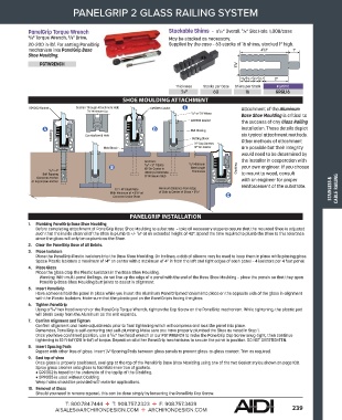
SHOE MOULDING ATTACHMENT
Attachment of the Aluminum
Base Shoe Moulding is critical to
the success of any Glass Railing
installation. These details depict
six typical attachment methods.
Other methods of attachment
are possible but their integrity
would need to be determined by
the installer in cooperation with
your own engineer. If you choose
to mount to wood, consult
STAINLESS & CABLE RAILING
with an engineer for proper
reinforcement of the substrate.
PANELGRIP INSTALLATION
1. Plumbing PanelGrip Base Shoe Moulding
Before completing attachment of PanelGrip Base Shoe Moulding to substrate – take all necessary steps to assure that the mounted Shoe is adjusted
such that the inside channel of the Shoe is plumb to +/- /8" at an extended height of 42". Spend the time required to plumb the Shoe to this tolerance
1
since the glass will only be as plumb as the Shoe.
2. Clear the PanelGrip Base of All Debris.
3. Place Isolators
Place the PanelGrip Plastic Isolators into the Base Shoe Moulding. On inclines, a dab of silicone may be used to keep them in place while placing glass.
Space Plastic Isolators a maximum of 14" on center with a maximum of 4" in from the left and right edges of each panel – 4 isolators per 4 foot panel.
4. Place Glass
Place the glass atop the Plastic Isolators in the Base Shoe Moulding.
Warning: With multi-panel Railings, do not line up the edge of a panel with the end of the Base Shoe Moulding – place the panels so that they span
PanelGrip Base Shoe Moulding butt joints to assist in alignment.
5. Insert PanelGrip
Have someone hold the panel in place while you insert the Aluminum PanelGrip mechanism into place on the opposite side of the glass in alignment
with the Plastic Isolators. Make sure that the plastic pad on the PanelGrip is facing the glass.
6. Tighten PanelGrip
Using a /16" hex head wrench or the PanelGrip Torque Wrench, tighten the Cap Screw on the PanelGrip mechanism. While tightening, the plastic pad
3
will break away from the Aluminum as the unit expands.
7. Confirm Alignment and Tighten
Confirm alignment and make adjustments prior to final tightening which will compress and lock the panel into place.
Remember, PanelGrip is self-centering and self-plumbing. Make sure you have properly plumbed the Shoe as noted in Step 1.
Once you have confirmed position, use a /16" hex head wrench or our PGTWRENCH to make the PanelGrip Cap Screw snug-tight, then continue
3
tightening to 10 ft-lbf (120 in-lbf) of torque. Repeat on all other PanelGrip mechanisms to secure the panel in position. DO NOT OVERTIGHTEN.
8. Insert Spacing Pads
1
Repeat with other lites of glass. Insert /4" Spacing Pads between glass panels to prevent glass-to-glass contact. Trim as required.
9. Seal top of shoe
Once glass is properly positioned, seal gap at the top of the PanelGrip Base Shoe Moulding using one of the two Gasket styles shown on page 108.
Spray glass cleaner onto glass to facilitate insertion of gaskets.
• GR9302 is taped to the underside of the top lip of the Cladding.
• GR9355 is used without Cladding
Weep holes should be provided with exterior applications.
10. Removal of Glass
Should you need to remove a panel, this can be done simply by loosening the PanelGrip Cap Screw.
T: 800.784.7444 T: 908.757.2323 F: 908.757.3439
AISALES@ARCHIRONDESIGN.COM ARCHIRONDESIGN.COM 239