|
|
|
|
|
|
|
Want to be a better CNC'er? Get our weekly newsletter plus a package of greatest hits, special tips, and more, all for free. I'm Ready to Be a Better CNC'er, Hook Me Up! |
Z-Axis Mount
The mill's Z-axis nut mount has to be modified to accept the ballnut. In addition, there is another mod to increase rigidty. These mods are done for you by IH if you send them the parts, but I decided to go ahead and do them myself for fun.
8/2/08
Z-Axis Ballnut Bracket Finished (Almost)
I felt a bit intimidated because an 18 TPI thread moves really fast and I didn't want to screw it up and have to make another or bush it or some such foolishness. So, there was a lot of careful measurement and horsing around, but the actual process was surprisingly smooth. Note that IH will do this work for you for free if you ask them.
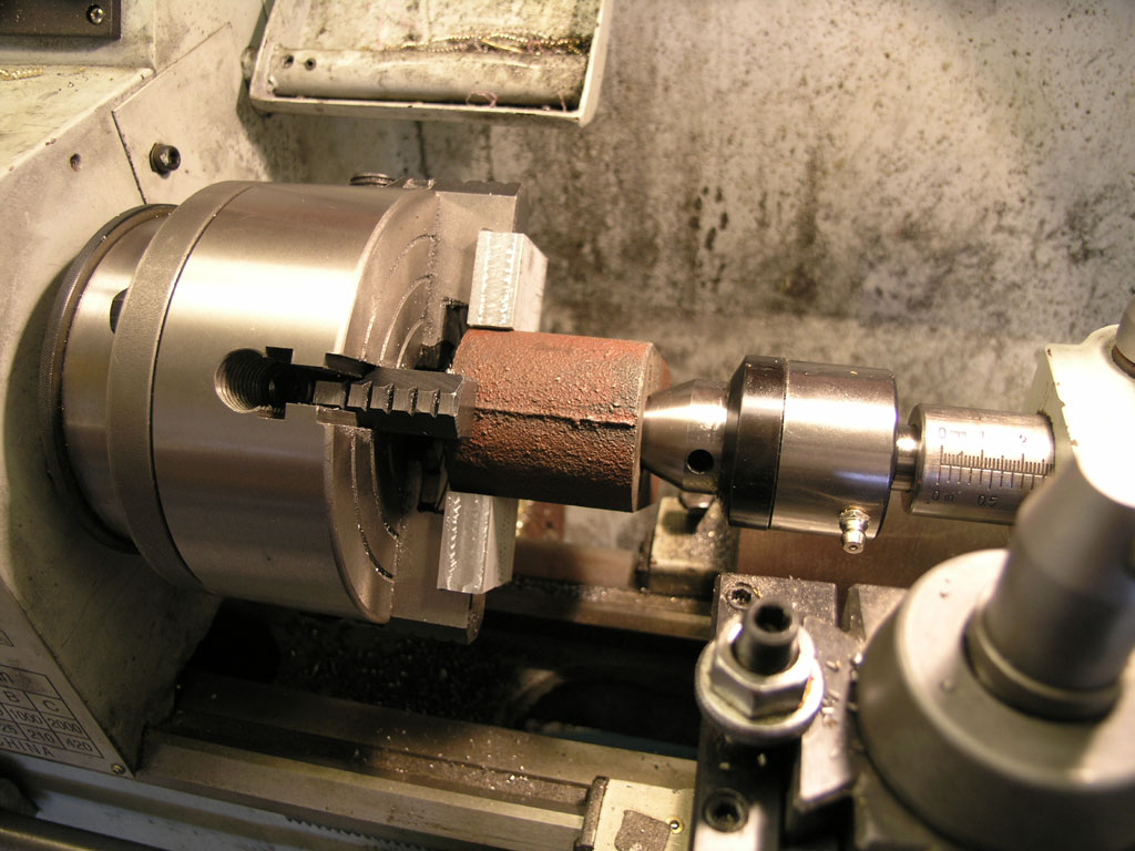
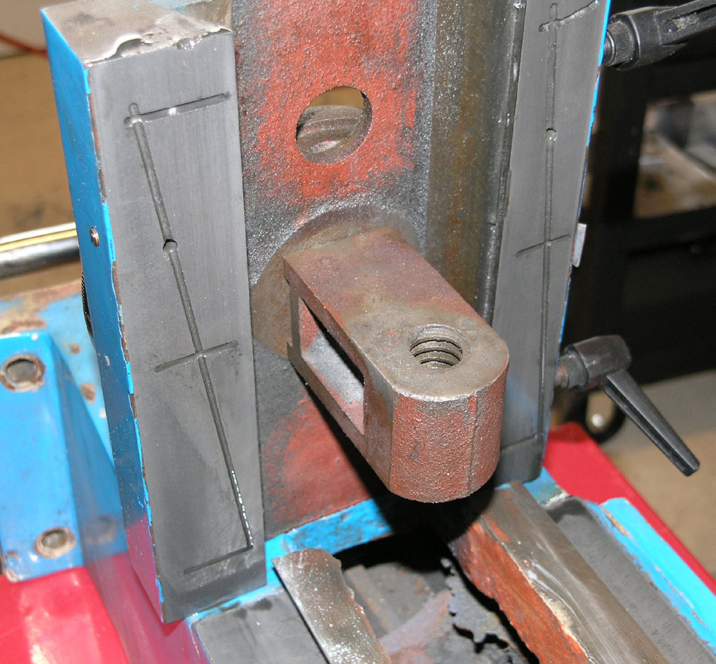
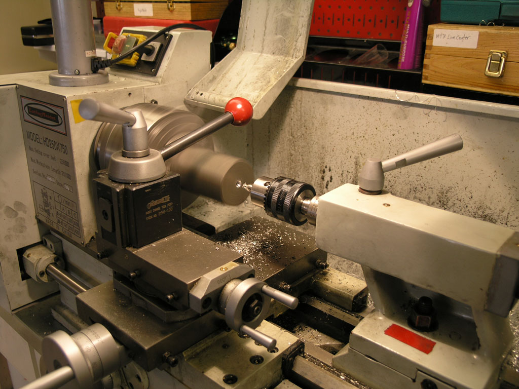
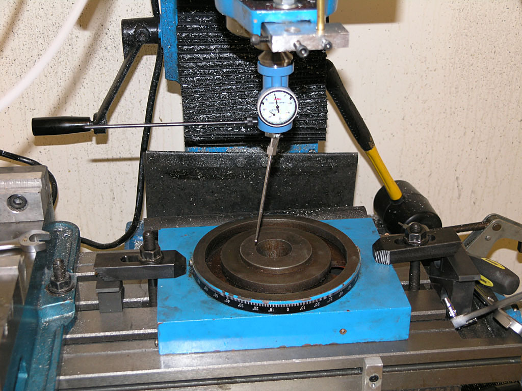
First issue was to line up on the bore. Every surface is rough and far from precision. I settled for this method where I lined up using the cone of a live center. It was close enough!
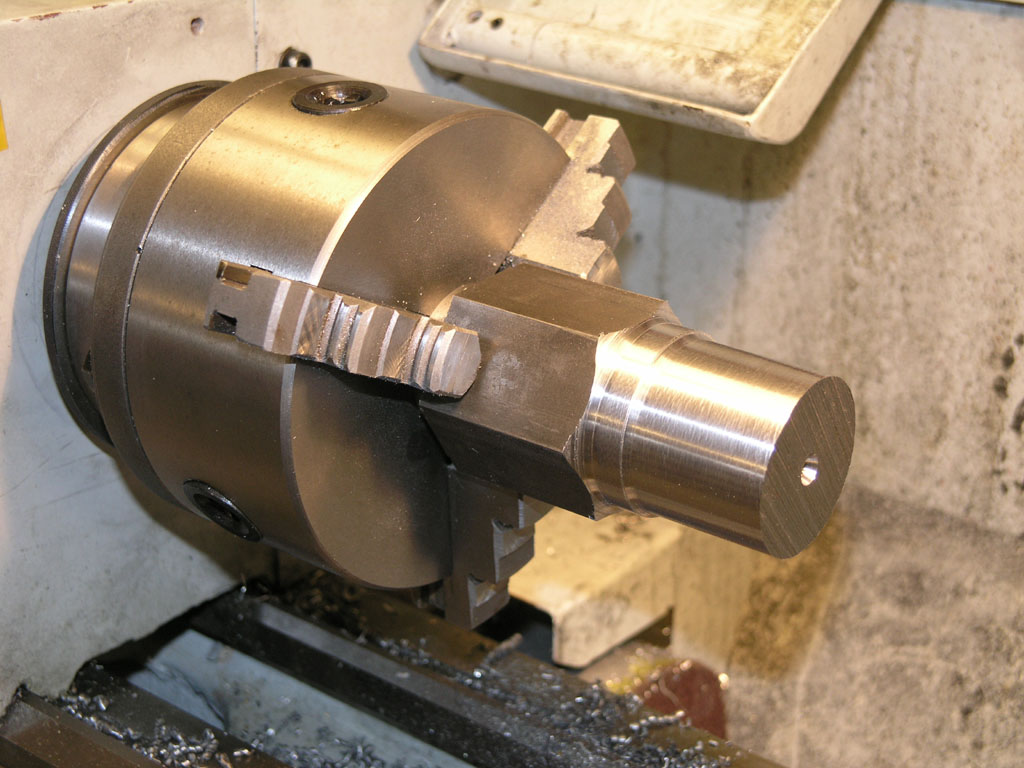
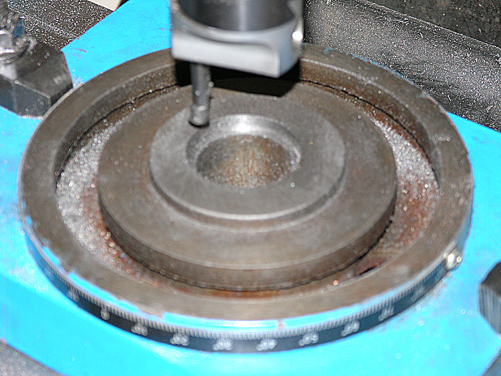
Next step was boring to the thread's minor diameter, which is 1.0649"
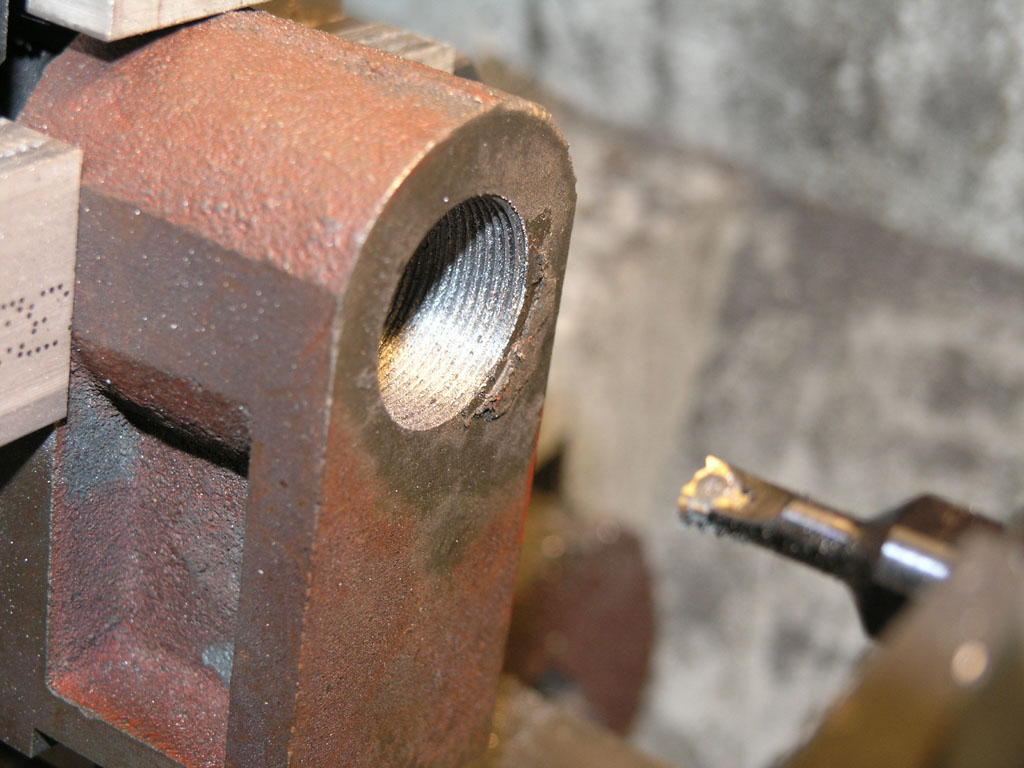
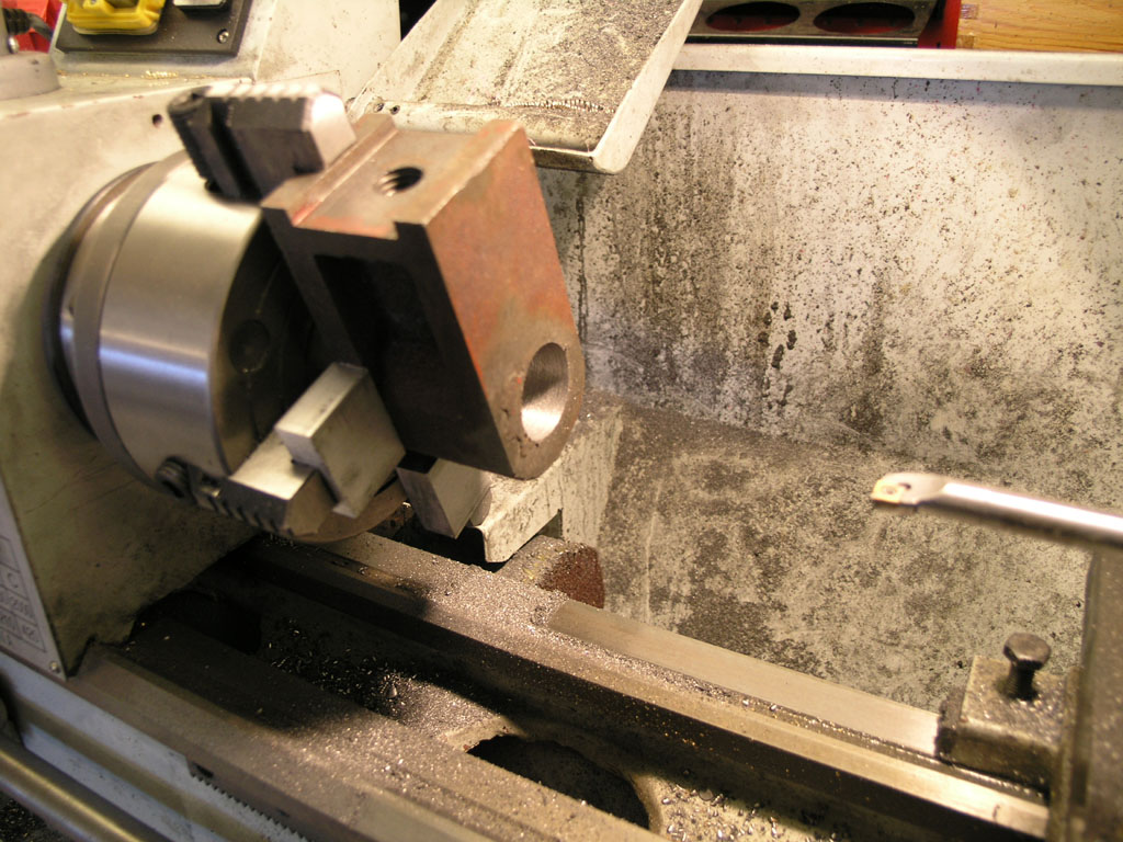
Here's what it looked like after a couple of passes with my Carmex indexable threading tool. I cut each pass less deep. Due to the triangular cross section, each pass is removing more material if you cut the same depth. As I recall, I used 0.010, 0.006, 0.004, and 0.004 to remove the total 0.024" required for the thread...
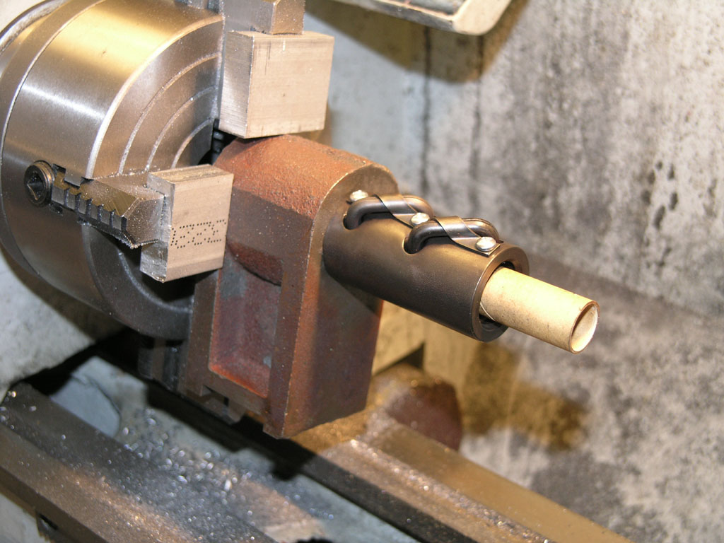
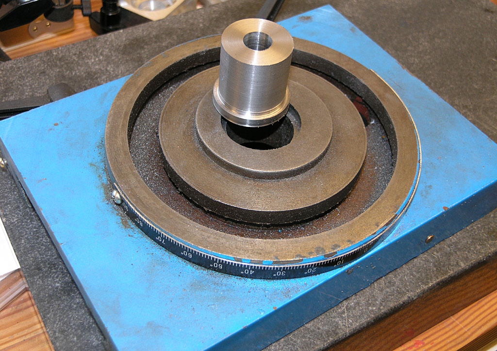
Fits like a glove!
What's left? I've been wondering how to route oil from the one shot system to the ballscrew and nut. I think what I'm going to do is mount this bracket to the Z-axis slide with the ballnut on the bottom, and the plumb a fitting to the side of the bracket to inject oil inside. Gravity will force the oil to run downhill.
7/26/08
Z-Axis Ballnut Thread Specs
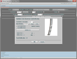
Doing my homework to see what kind of internal thread I need to cut. Looking at the ballnut and the Rockford web site, it looks like I want a 1.125 - 18UNEF internal thread. My Machinery's Handbook tells me the following about this thread:
Basic Pitch Diameter: 1.0889"
Minor Diameter: 1.0649"
So I'll need to cut an internal bore that's 1.0649" in diameter and then cut the threads an additional (1.0889 - 1.0649) = 0.0240" deep. Here is my plan:
1. Bore one side of the Z-axis mount to 1.25" diameter to accept a wiper. Note: need to set this up like a snap ring groove, so need to think about this!
2. Bore the other side of the Z-axis mount to 1.0649".
3. Set up to thread. Spindle speed will be 1/4 normal turning speed. Set belts to lowest speed range to ensure torque.
4. Chamfer the end of the work to just under 1.0649"--let's say 1.060".
5. Measure where the threads will end and mark the threading tool with a piece of tape.
6. Set up the threading tool and set the cutting depth so the tool just lightly marks.
7. Adjust for a 0.001-0.003" depth of cut.
8. Take a pass. Check the pitch with a thread gage.
9. Finish cutting until we get to a depth of 1.0889". Each successive pass should cut a little less depth because we're widening the cut each pass. For example, 0.010, 0.006, 0.004, 0.004 would remove 0.024".
2/23/08
Started Installing the One Shot Oiling System: Z-Axis Modifications
I got started with my one shot oiling sytsem by cutting oil distribution grooves in the Z-slide. It works well!
I tried it out and got a wonderful even distribution across the ways...
Finished Up the Z-Axis Mod
With the shoulder cut on the saddle, next step was to make the matching bushing. The only material I had large enough in steel (I've got a lot of aluminum) was some 12L14 hex stock:
Center drilling...
Some initial turning done...
Got the final OD's completed, so I'm parting it off. If I was being finicky, I should've done the center hole before parting to maintain concentricity. But, this is a low tolerance part and I too impatient to try it out in the saddle for fit...
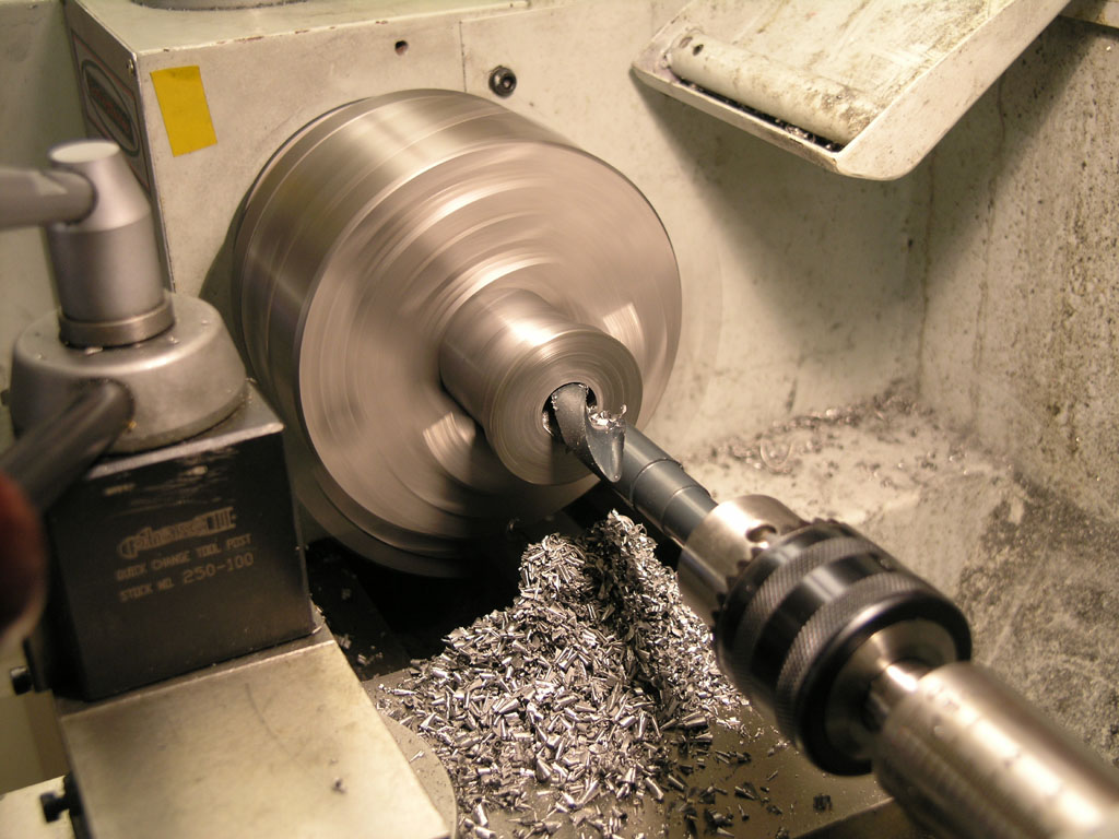
Silver and Deming to bore the center hole...
Yep, it fits...
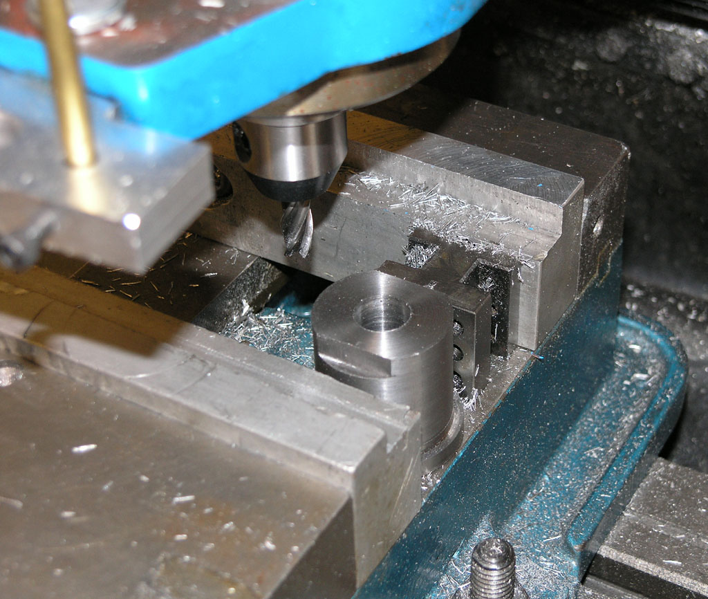
I didn't take pix of the counterbore on the other side. I used the coaxial indicator to line up the counter bore and a Silver and Deming bit in an R8 collet to drill it. Here I am cutting the flats with a 1/4" 4-flute end mill that mate against a slot in the ballnut bracket...
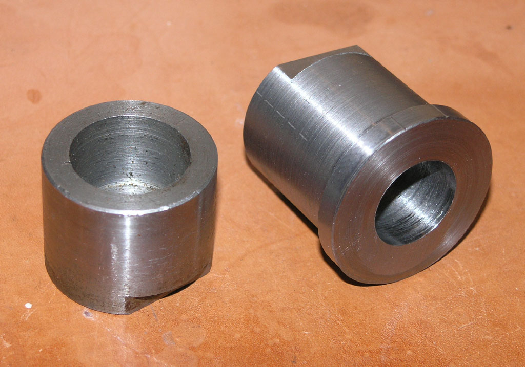
You can see the finished bracket versus the original. It not pinches the ballnut bracket against the saddle and locks everything up firmly. There'll be no more slop here!
There's what the backside looks like. Note my new oil grooves...
2/22/08
Started to Modify the Z-Axis
There is a significant source of slop in the Z-axis that requires a modification. This is the bracket that attaches the Z-axis slide to the leadscrew. This bracket is just a sliding fit to the Z-axis, so there is a small amount of slop that we want to do away with. The modification is described on the Industrial Hobbies web site, and can be done to almost any RF-45 mill. It involves creating a new bushing that has a shoulder on it so that you can bolt it down and squeeze the Z-axis saddle between the shoulder and the leadscrew bracket.
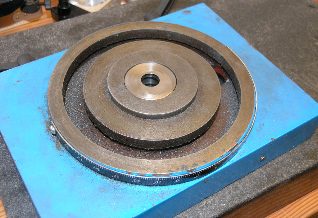
For this job, I got to try out my new Shars Coaxial Indicator. It's a lot cheaper than a Blake and I'd heard they're pretty good from Swede (5Bears) over on the HMEM boards. Here is the coax in an R8 collet being used to center the spindle over the hole I want to make a shoulder on:
Coax indicator preparing to dial in the spindle so it is centered on that hole...
Picture that long feeler as being sort of like a very exagerated finger from a dial test indicator. It goes against the inside of the hole, or there are curved feelers for the outside of a round boss. You turn on the spindle at the lowest rpm, say 100rpm, and hold the horizontal rod. This keeps the indicator facing your way. Now adjust the X and Y axis handwheels until the needle kicks as little as possible. That's all there is to it, you are done very quickly. What a nice gadget!
Adjust the axes one at a time and don't even think much about what's needed. Simply turn the wheel and observe whether the needle kicks more or less. Turn it in the direction that kicks less. When you've minimized the kick on one axis, do the other. I circle back a second time around and got to almost no kick at all.
I did not set up the Indicol and DTI to check the result as I was in a hurry, but visually, after I used the boring head to make the shoulder, it looked spot on.
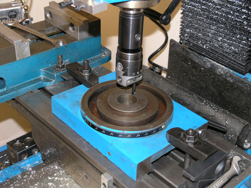
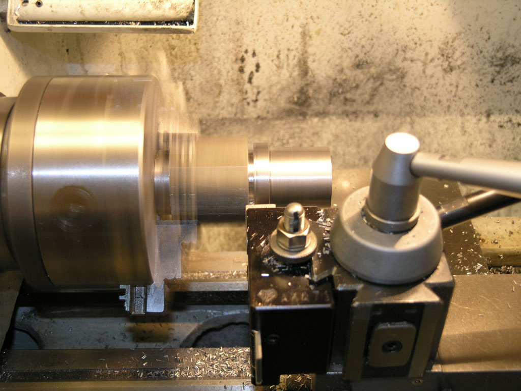
Here is the boring head gearing up to cut that shoulder...
Sorry for the blurred pic, but you can see the shoulder is well centered on the hole...
|
Do you want to be a better CNC'er? Get Better Tool Life, Surface Finish, and Material Removal Rates.
|
||||||||||||||||||
| ||||||||||||||||||