|
|
|
|
|
|
|
Want to be a better CNC'er? Get our weekly newsletter plus a package of greatest hits, special tips, and more, all for free. I'm Ready to Be a Better CNC'er, Hook Me Up! |
Axis Modules: CNC Servo/Stepper Drivers
The Axis Module Concept
I've decided to house a number of components associated with a CNC axis in what I call an "axis module". The axis module takes in DC power and step/direction signals and has external connections to the servo (power + encoder) or stepper (just power) motor. Assembling all of the components associated with an axis onto a little sub-chassis just makes for cleaner electronics and a neater design.
A typical Axis Module contains the following:
- Front panel: This is an aluminum or steel sheet metal plate that mounts in a cutout on the NEMA enclosure.
- Geckodrive: Either a sepper or servo drive may be used. For example, I plan on setting up this enclosure with the full 6 channels Mach 3 can control. 4 axes will be servo (X, Y, Z, and the "A" 4th rotary axis) and 2 axes will be stepper for an Automatic Tool Changer I'm planning to build.
- Heatsink: The Geckodrive will be mounted on a heatsink for maximum durability and performance.
- Fuse: a 3AG style fuse will be provided for each axis that can be accessed to check or change the fuse from the front panel.
- Power connection for the stepper or servo.
- Optional encoder connector for sevos.
- Optional load meter.
Here is a 3D model that gives an idea of how the Axis Modules are laid out:
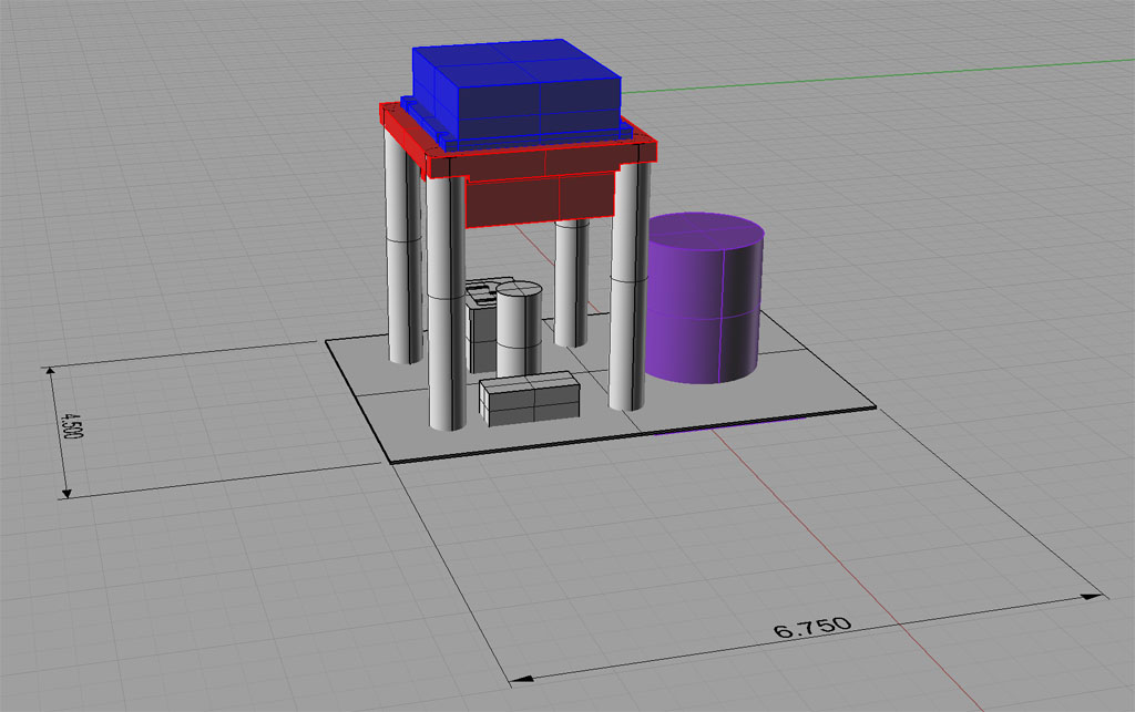
The module is laying face down. Blue box on top is the Geckodrive. The red underneath is a heatsink. Purple is the back of the optional Load Meter. The three components below the load meter are from front to back the optional servo encoder connection, the 3AG fuse holder, and an IEC power receptacle that I plan to use for the power connection on my servos.
Machining the Heat Sinks
I'm making 6 axis modules. For the heat sink, I'm using a large piece of really nice heat sink material I got off of eBay as surplus. Follow along with the photo tutorial and how I machined these:
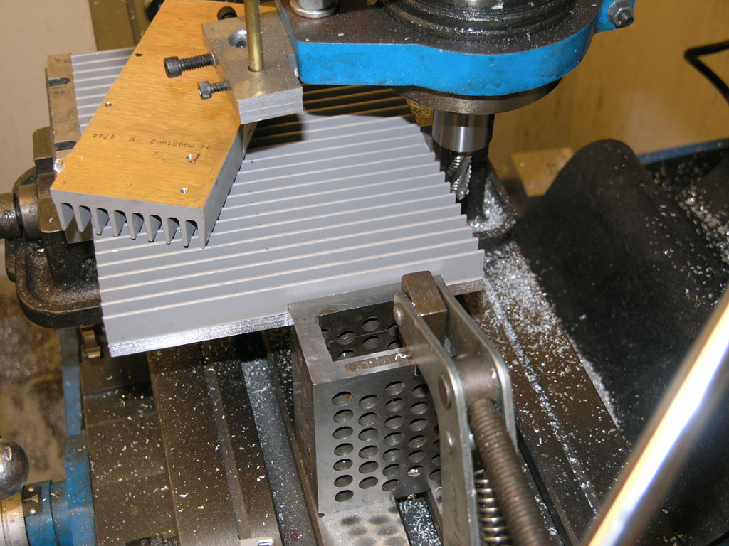
The initial heat sink was a single large piece--too large for my bandsaw or chop saw. So I used a 1/2" roughing end mill to cut it into strips of the right width. Note the precision block being used as a stop.
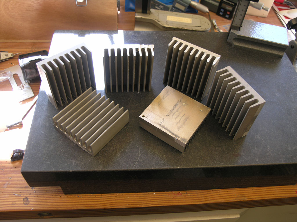
Once I had strips it was a simple matter to use the chop saw to create the individually sized heat sinks for each of the 6 axis modules...
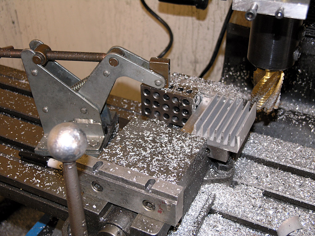
Next step is to mill a 1/2" off either side. This is where the mounting holes will be drill and tapped for both the Geckodrive and the spacers that hold the heatsink. Note the big 1" corn cob cutter. I tried 3 different cutters. First up was the 1/2" corncob you saw earlier. Next was a 3/4" APKT indexable end mill. The big corn cob did the best job by far so I used it for 4 of the 6 heat sinks. Man you can sure make some chips fly with that cutter!
It's easy to make a 1:1 scale drilling template with the CAD program. I went an extra step and used it to carefully set up a little piece of steel plate so now I have a template + jig. Made things a lot faster, easier, and more accurate. Once I get CNC, this will be an obsolete technology though!
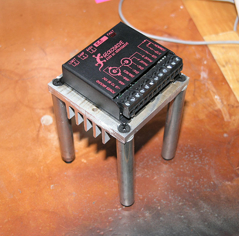
Martian war machine? The legs are some stainless I had kicking around. 304, unfortunatley, but I had some nice new 8-32 spiral flute taps that made it a little less unpleasant...
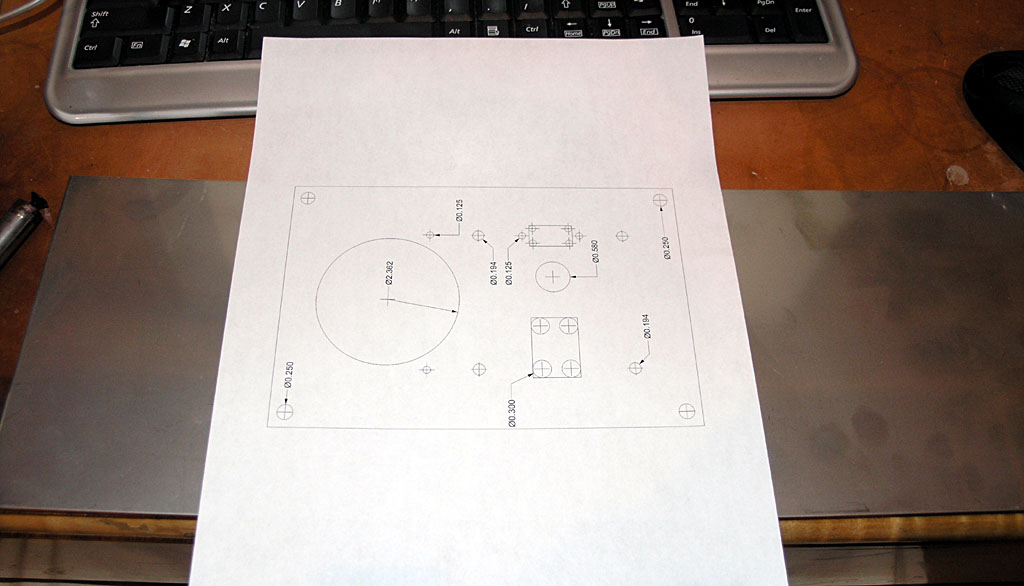
Overlay for the sheet metal printed 1:1 so I can use it as a template...
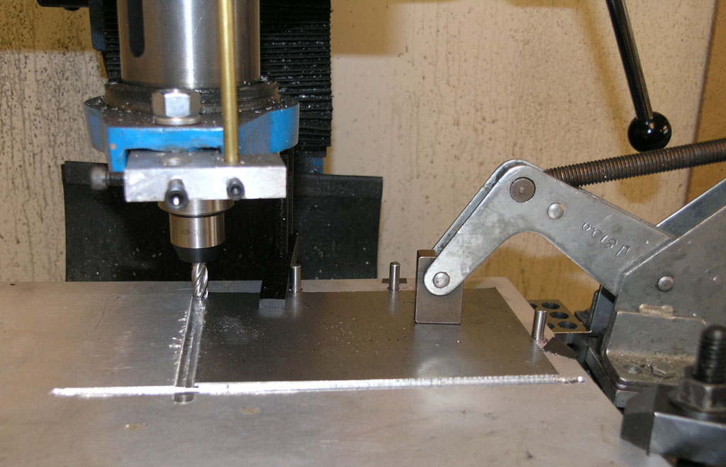
I made a quick and dirty fixture plate out of aluminum 1/4" cast tooling plate. All it took was drilling and reaming 3 1/4" dowel pin holes and Loctiting the dowel pins in place. Using the pins, I have an easy way to precisely locate each plate to the exact same position. Here I am milling to size.
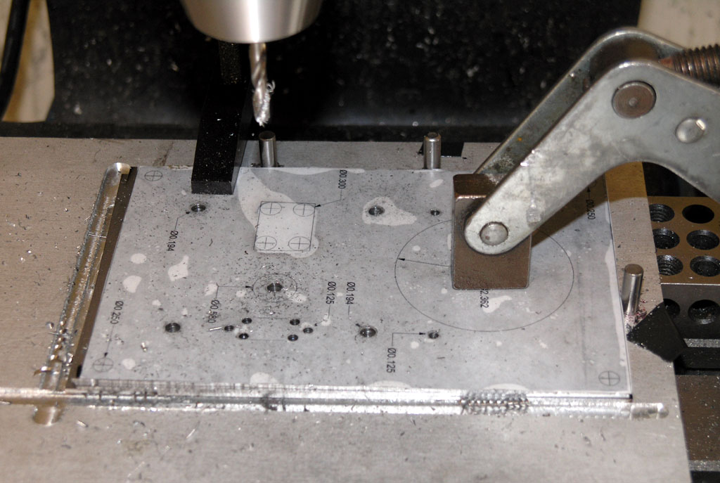
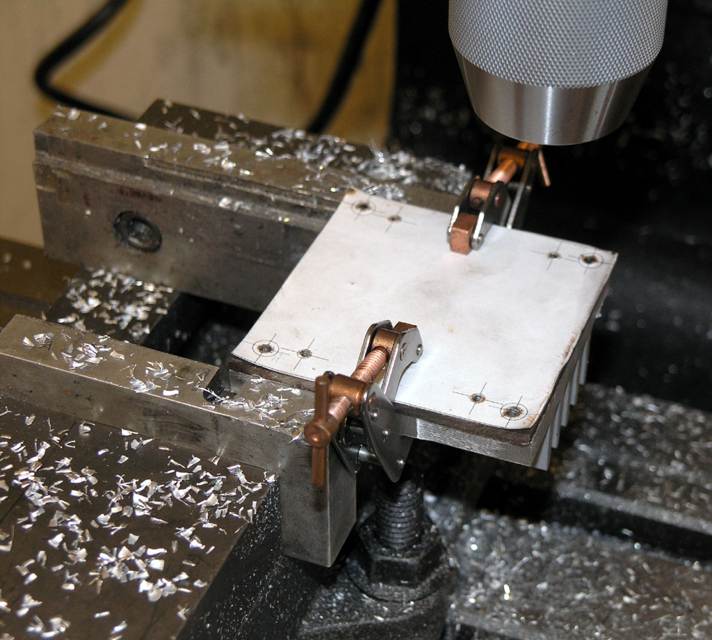
Cut out and lay the paper template on and then clamp the works down. Spray WD-40 on to keep the template down against the plate. Now every hole is marked and it is a simple matter to slew the table around and get them all drilled.
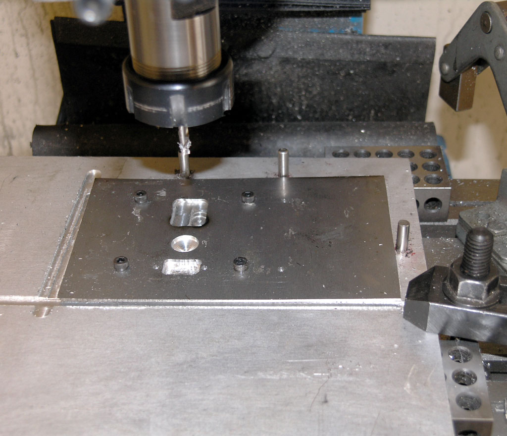
Next step is milling the larger cutouts with a 1/4" end mill. I had drilled out the holes at the corners in advance. In this case, I am using 4 of the holes together with some 10-24 socket head cap screws to ensure the plate is really held down tightly. Cutting in some directions will climb mill which I have found tends to make the plate want to slip in the clamps almost no matter how tight I got them. Bolting it down provides a fail safe means of preventing this. Since I had drilled the corners of each cutout, I didn't work very hard to get the plate preciely aligned. I'm just using the endmill to "connect the dots".
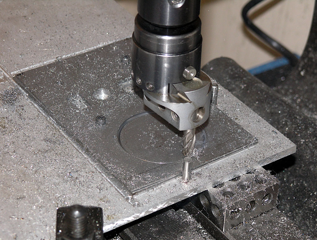
Last step is the meter cutout. This requires a 2.370" hole. Historically, I have not had great luck cutting holes like this in sheet metal, and this was no exception. It looks like things are going pretty well there, and they were. I took a 4 flute endmill out of the dull/scrap bin and went after it with my tool grinder. The idea was to expose just one flute and provide clearance to cut the groove as shown. It cut amazingly well on the first sheet, but things got progressively worse on the second and I gave up on the third. I should say that my sheet metal is mystery steel and not aluminum. My suspicion is that it was work hardening on me, because the cutter would go along pretty well, then it would start to throw sparks, and then it would simply snap off. Doh!
I'm going to have to do something different on that last hole, and I am resolved to do something pretty radically different because I'm tired of having trouble making big holes in sheet metal. Ironically, if I had the CNC working, it would be straightforward to do an interpolated circle for the cutout and I would be done. Meanwhile, I located a really nice punch and die set for my hydraulic press on eBay called a "Unipunch". I aim to give that a whirl when it arrives. If nothing else, I will learn something new from it.
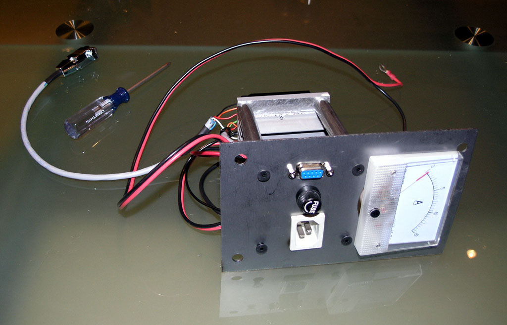
Meanwhile, I did get 2 module panels made, so here is what a module looks like with a few more parts installed:
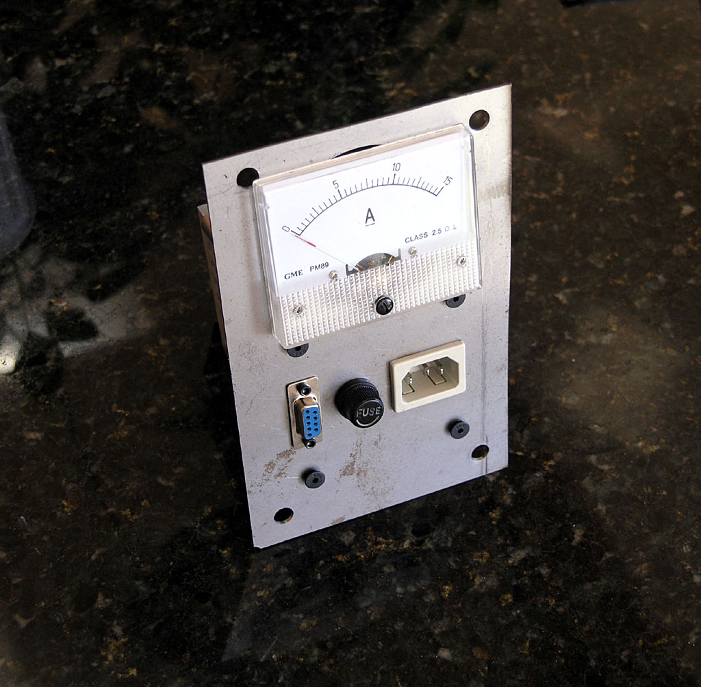
As you can see I have an issue with meter clearance and the mounting bolts, so I made an oversized hole to try to create some "wiggle room". This happened due to an error in laying out the big square face during the CAD design. What I need to do is relocate the whole meter 1/4" down the panel and all would be well.
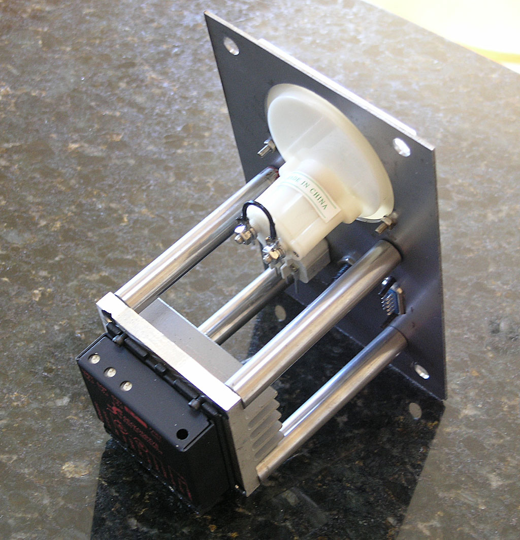
I've gotten it close enough, I think. I can't go much further or I'll lose the mounting holes for the meter as you can see in this behind shot. In the end, I'm planning to remake these panels anyway once the CNC is up and running. I'll make them out of 1/4" aluminum plate and put some engraving and other decorative touches on so they'll look a lot nicer and the panel meter will be exactly where it needs to be.
Wiring Diagram
Here is the wiring diagram for an axis module:
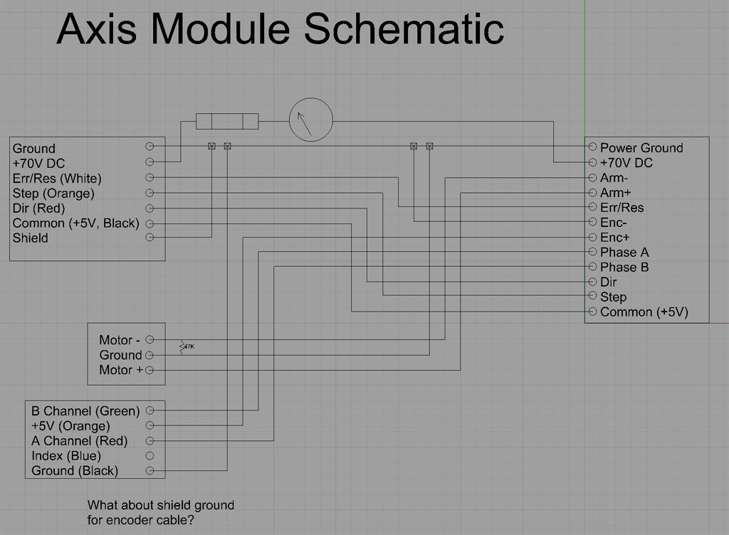
Preliminary, and for informational use only. Do not use as a plan for your CNC machine!
A few things to note. First, the 47K ohm resistor between Motor - and Ground was recommended by Mariss F. if you have any issues with power on faulting. It seems this helps make sure the bridge inside the drive initializes correctly and it will be built in to the next gen Gecko servo drives. Second, I have grounded absolutely everything that goes to ground to the same ground. Opinions differ wildly on best practices for grounding. Some like to keep the DC power supply ground separate from any digital circuitry because they feel it makes for better noise rejection. I'll have to see how this works and may have to revisit my grounding practices.
The Finished Module
Here is a finished, tested module with a quick disconnect for the signal level lines made out of a DB9:
|
Do you want to be a better CNC'er? Get Better Tool Life, Surface Finish, and Material Removal Rates.
|
||||||||||||||||||
| ||||||||||||||||||