|
|
|
|
|
|
|
Want to be a better CNC'er? Get our weekly newsletter plus a package of greatest hits, special tips, and more, all for free. I'm Ready to Be a Better CNC'er, Hook Me Up! |
Y-Axis Ballnut Mount Modifications
The ballnut mount that comes with the IH CNC kit has a peculiar design shortcoming. Like many such mounts, it incorporates a flange with 4-bolts that are used to attach the mount to the underside of the saddle. The ballnut then threads into this mount and this is how the saddle is driven in Y. If we look at the ballscrew as running "in and out" for the Y-axis, these 2 flanges are at top and bottom.
The peculiarity is that Inudstrial Hobby's installation instructions recommend cutting off the back flange to allow more travel. In addition, the suggest reusing the old mounting hole that comes down vertically through the ways to anchor the rear of the mount. They warn its a touchy operation if you drill too deep and release chips into the ballnut assembly. Quite aside from it being touchy, I didn't like the idea of 3 bolts instead of 4 holding this piece. Looking at it, I couldn't see why the flanges had to be fore and aft instead of left and right. It doesn't look to me like there is any interference if we make them left and right. Since this is a very easy part to make, and I already had to do the same bore and threading job for the Z-axis ballnut, I decided to make a revised mount for my mill in hopes of increasing rigidity and performance. Not only will this mount be more solidly attached with 4-bolts, but there will also be a bit more aluminum in the mount.
On with construction photos!
I first did a quick drawing of the old and new mounts in Rhino so I could make sure my dimensions matched the old one where it counts:
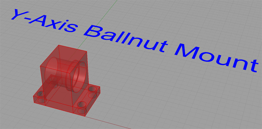
Here is the old mount. The flanges are in line with the ballscrew...
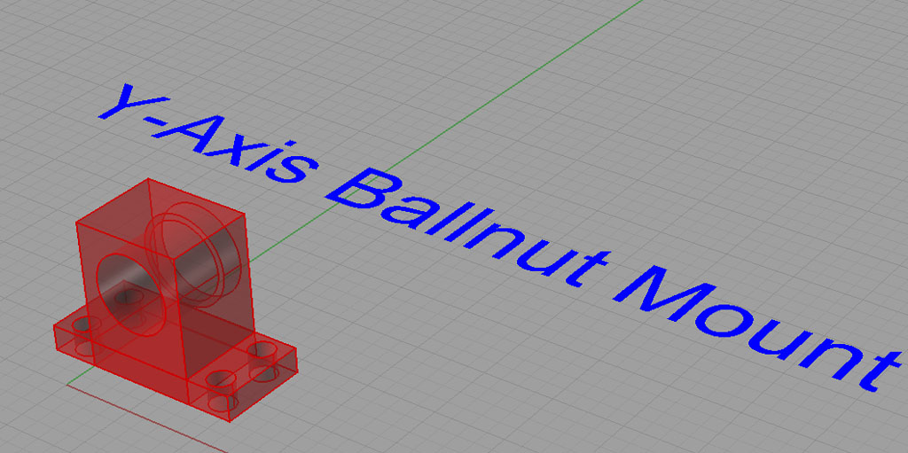
The new mount places the flanges on either side of the ballscrew...
Once I had a set of dimensioned drawings, machine work commences:
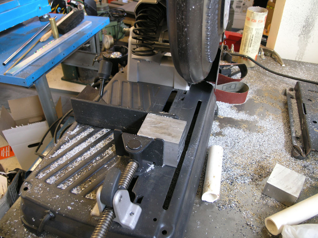
These things generally start with a saw...
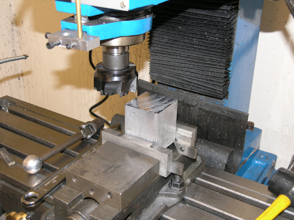
Next we get out the face mill and square the block...
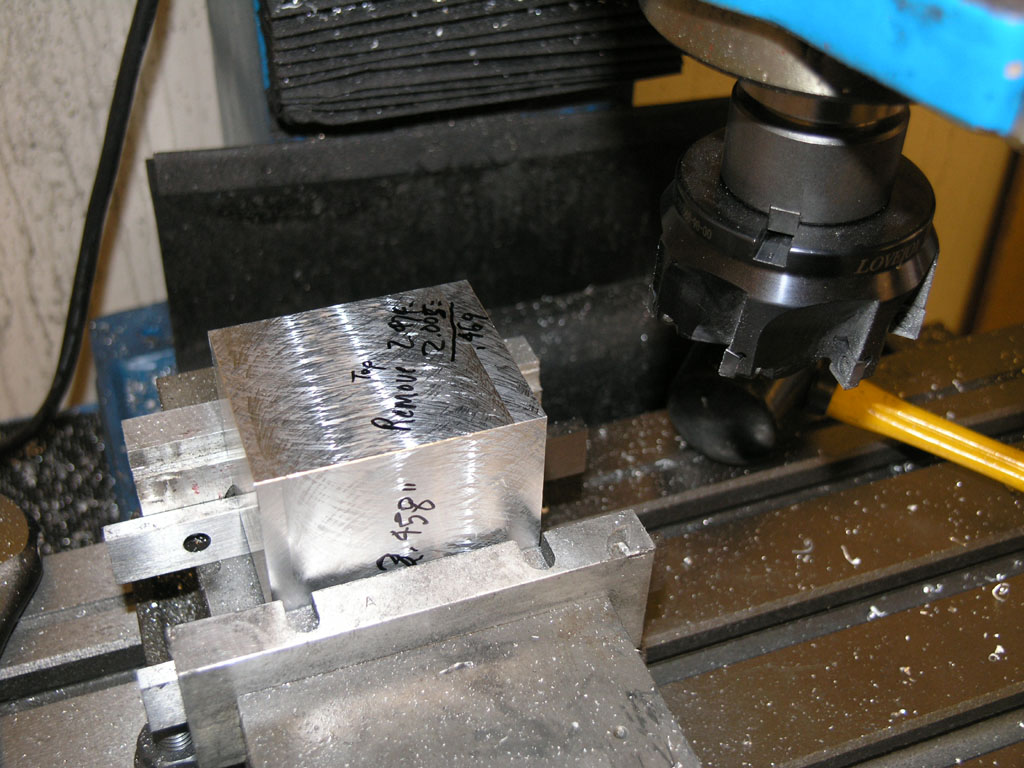
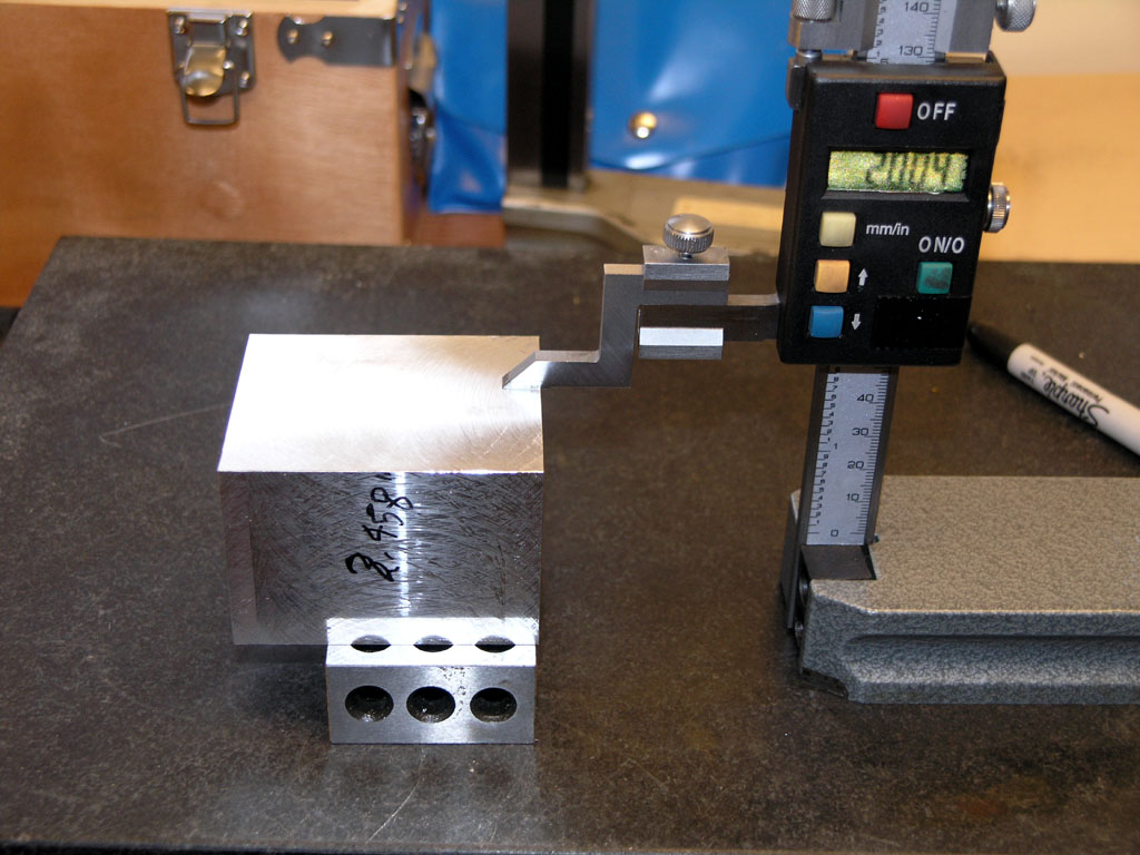
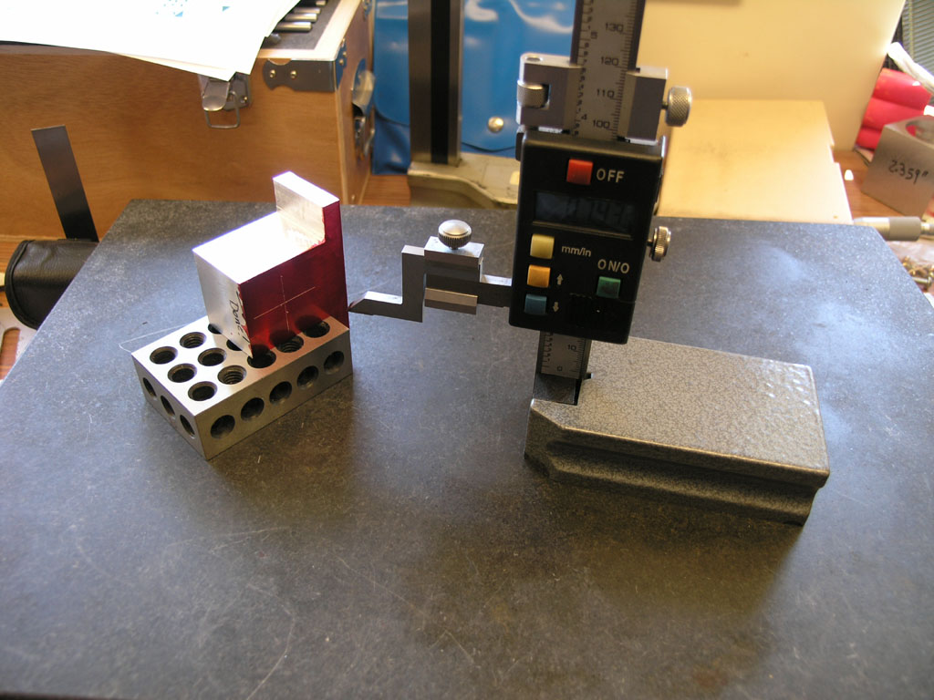
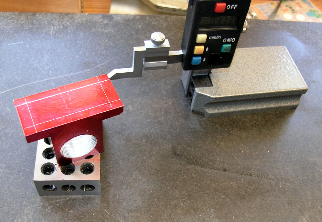
Once squared, I use my granite surface plate and height gage to measure the thickness on each of the 3 dimensions and I write that on the block. I orient the top first and we'll shave it down to the correct dimension. Note the cutter marks are equal both ways. That means the cutter was cutting on both sides and the mill is in tram. These were pretty rough cuts (0.040-0.050 DOC) since we are not finished with any of these edges...
Given the height of the block, and the desired height, we know how much to remove. First step is to color a little block in and gently bring down the face mill until it just scrapes off the marker ink. Now we know we're right at the height of the block. I zero the quill DRO and I'm ready to start taking passes to shave this block to size...
I measured the IH block at 2.003" high and I was shooting to add 1 thou just in case. Got it dead on! To accomplish that task I needed to remove 0.479". I took the block down to 0.400" with deep cuts, took it off the mill, remeasured what was left to remove. Note that the block was warm and I chilled it back to room temp before measuring. It shrank about 0.004" after cooling! Now I knew I needed to remove 0.069" (my 0.400" goal was not quite dead on due to the deep cuts and workpiece warming) to get to final thickness...
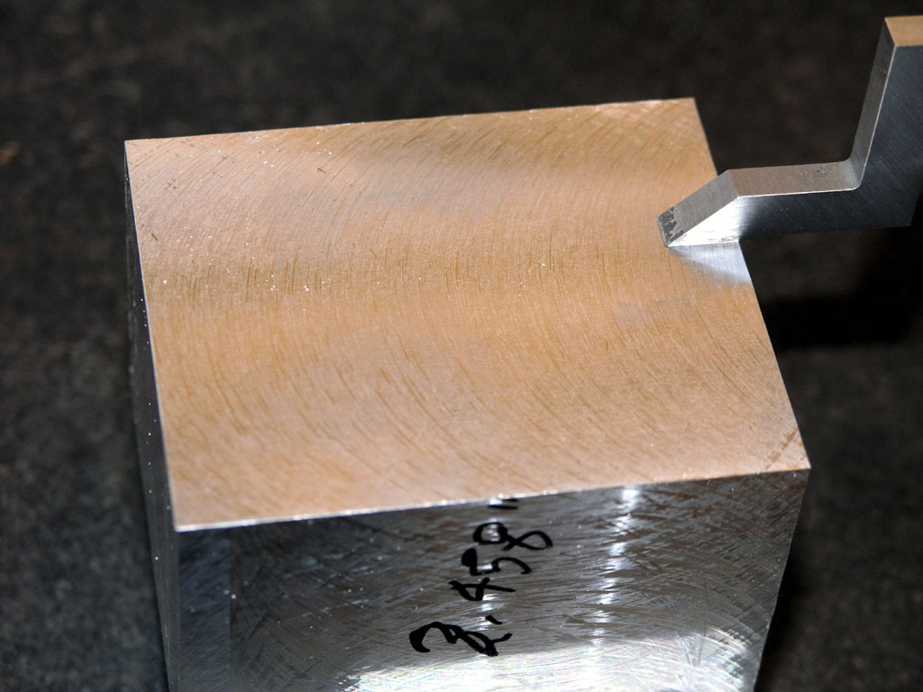
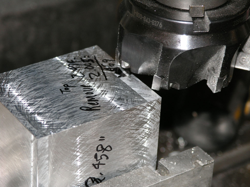
The last cut I made was 0.006". With this indexable cutter at 2000 rpm and a very slow feed (one handwheel turn per 3 seconds), the finish came out very nice. The photo doesn't do it justice as it almost looks ground...
One of the three dimensions is done. We've got 2 more to do and then we can start putting some features on this block.
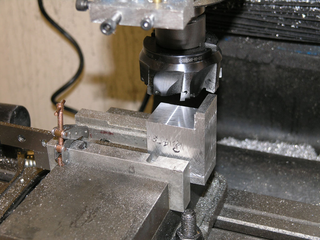
Once the basic 3 dimensions are sized, the next job is to cut the flange. I just kept right on using my face mill for this. I've just finished the first flange. Minor booboo is visible, but it will cause no harm. Note the block is on parallels, and I'm using a 3rd parallel as a vise stop...
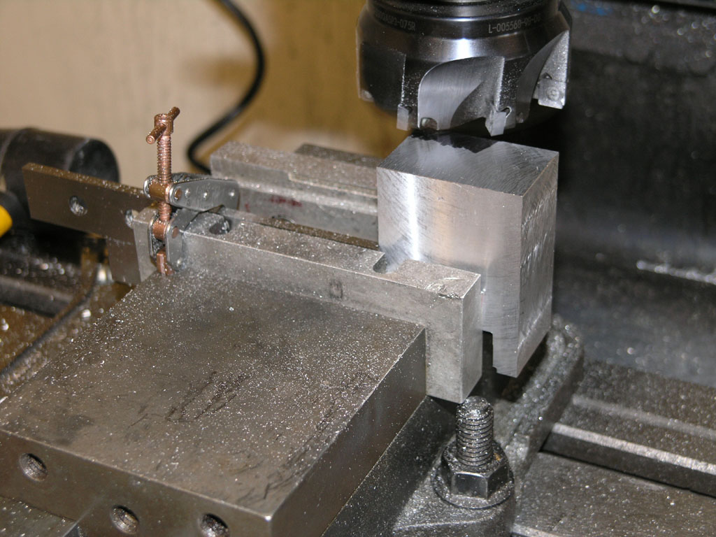
With a vise stop, the 2nd flange is easy, just flip the block and start taking passes--the cutter is already in the right x position to match the flange thickness of the other flange. That's why I set the block a little outside the vise jaws on the first step!
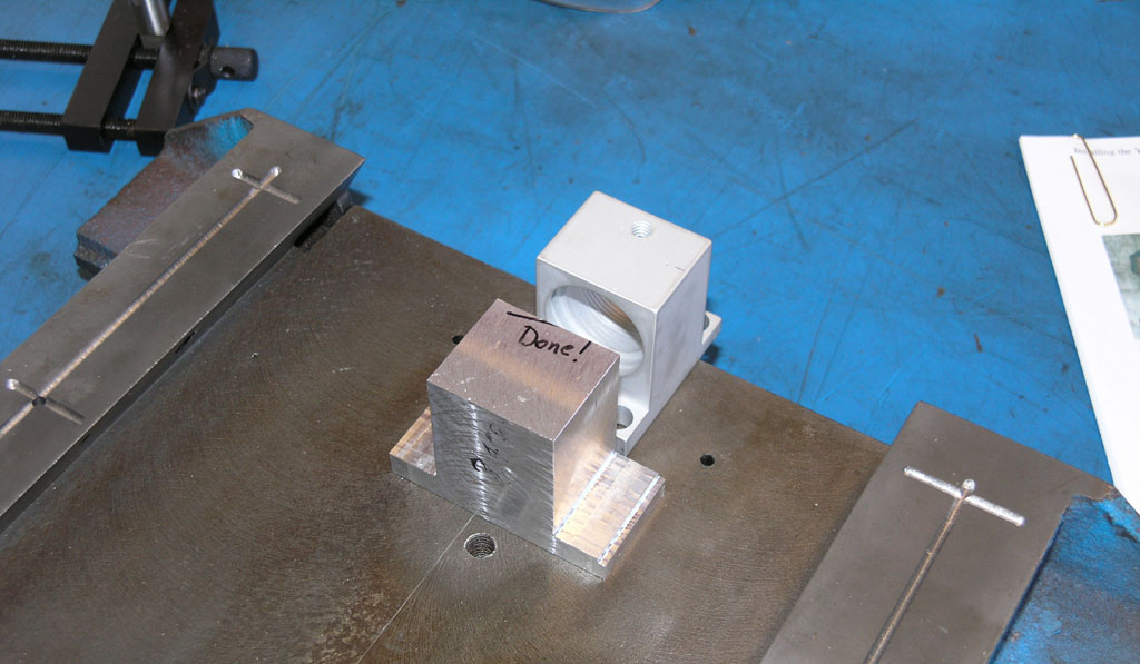
After using the face mill to create flanges, here is the result. I've positioned the IH kti mount as it is intended to be installed, albeit they intend for that back flange hanging off the edge to be milled off...
My new flange will sit just like this...
After applying some Dychem, I'm marking out the bore center...
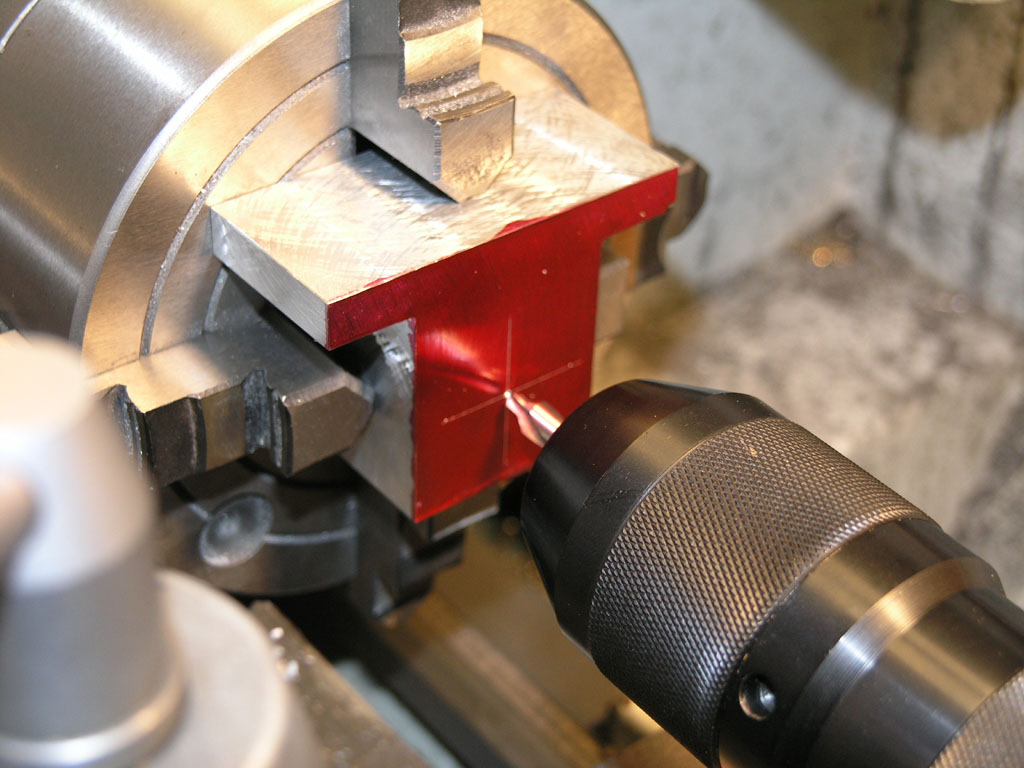
Sorry, forgot to take a pic of aligning the 4-jaw on that center punched mark. Trust me, I used an indicator technique and didn't just line up by eye on the center drill!
After center drilling I used a 1/2" screw machine length twist bit...
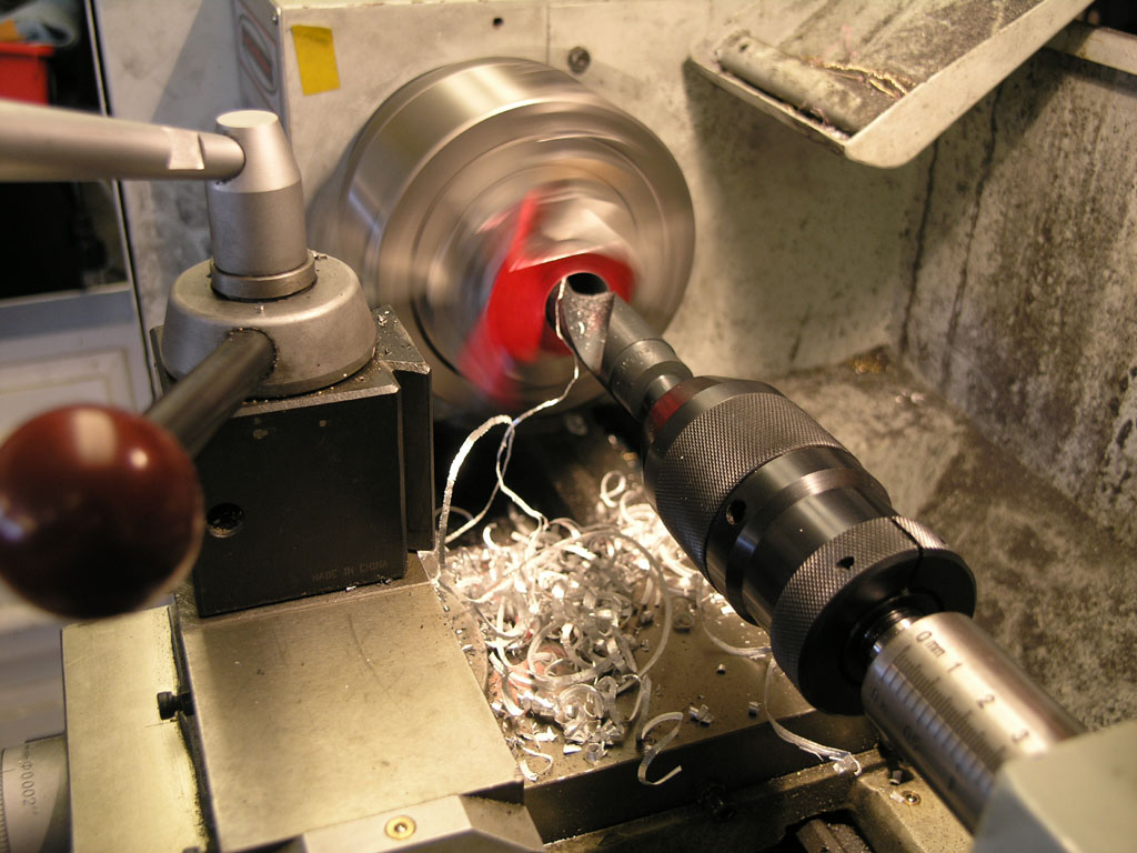
Followed by a 15/16" Silver and Deming bit. You may as well twist drill to pretty near the bore so there is less to remove with a boring bar...
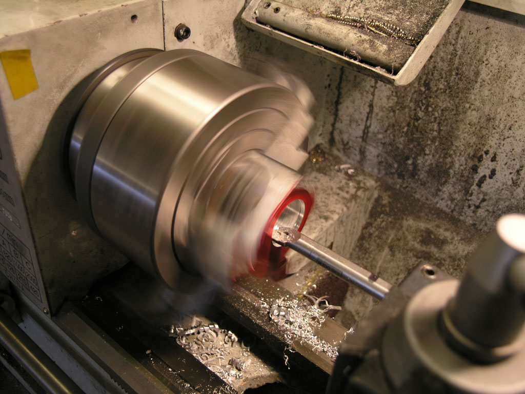
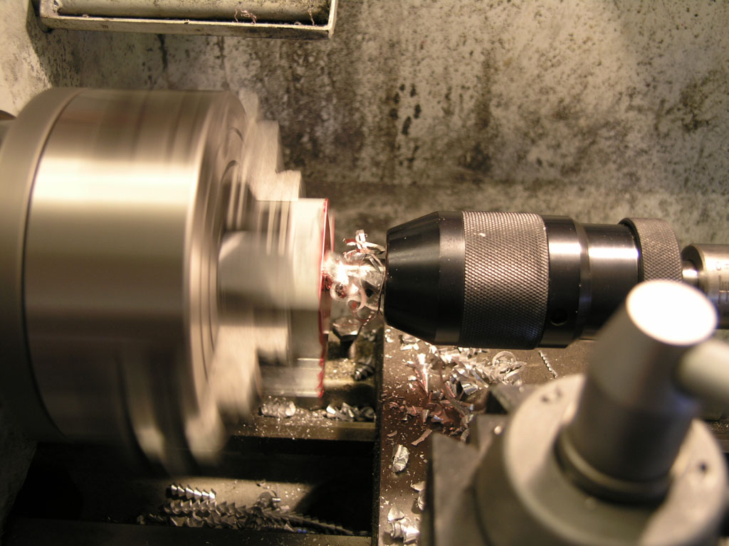
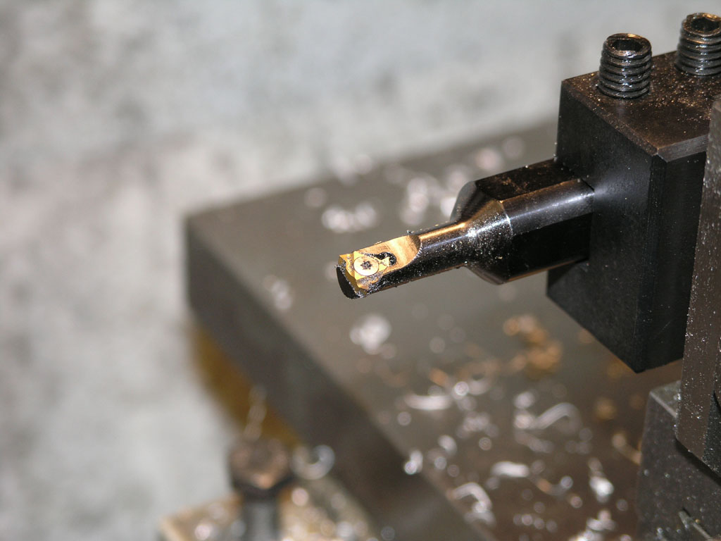
There goes said boring bar. It's a CCMT insert Micro-100 bar. I have it hanging out way too far here, but it worked fine! Similar to the Z-axis mod, I bored to the thread's minor diameter all the way through to the other side...
After boring I got out my trusty Car Mex threading tool...
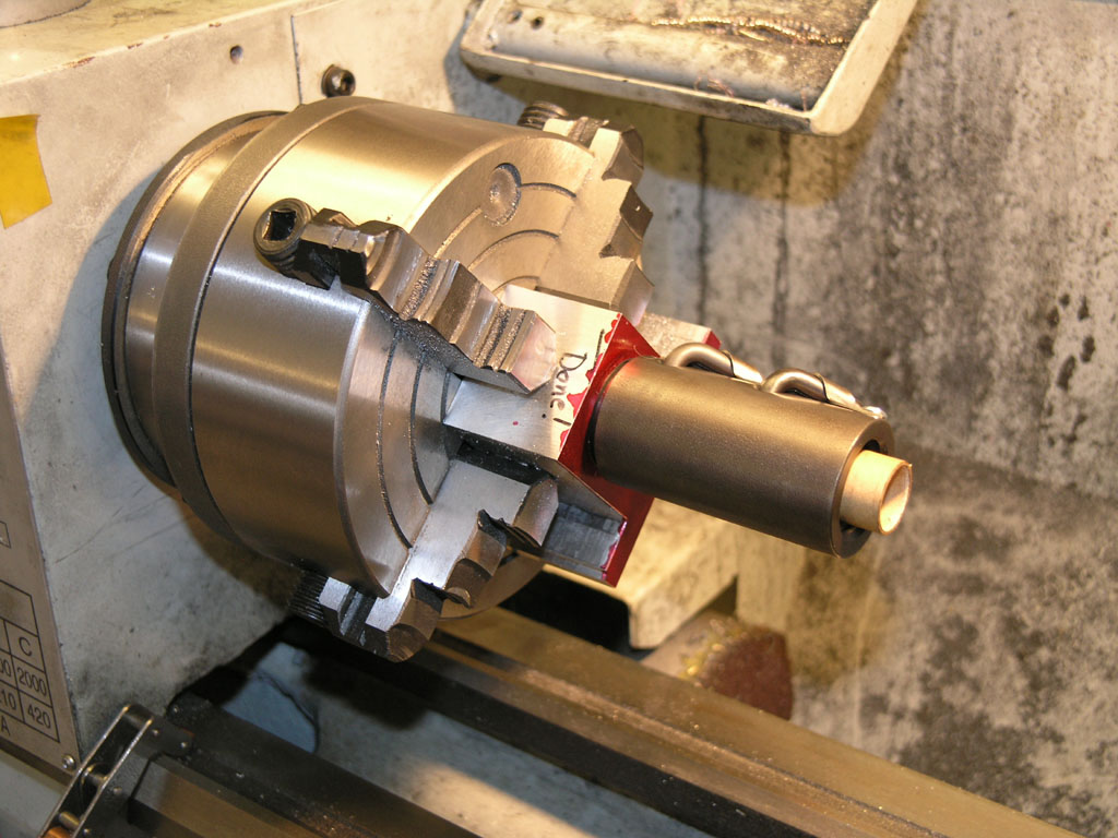
And pretty soon I was able to screw the ballnut into the mount!
I had 2 other pressing issues to deal with, so that was it for the afternoon's work. I had to press a shaft straight on my disc grinder after it fell on the floor (DOH!) and I needed to help my brother build a saddle bag bracket for his motorcycle. We fixed the sander and made decent progress on the bags. I'll get back to finishing this almost done bracket pretty shortly!
Okay, I admit it. I forgot to take pictures while I flipped the part in the 4-jaw and machined a larger bore for the wiper and a groove for a retaining ring. Sorry!
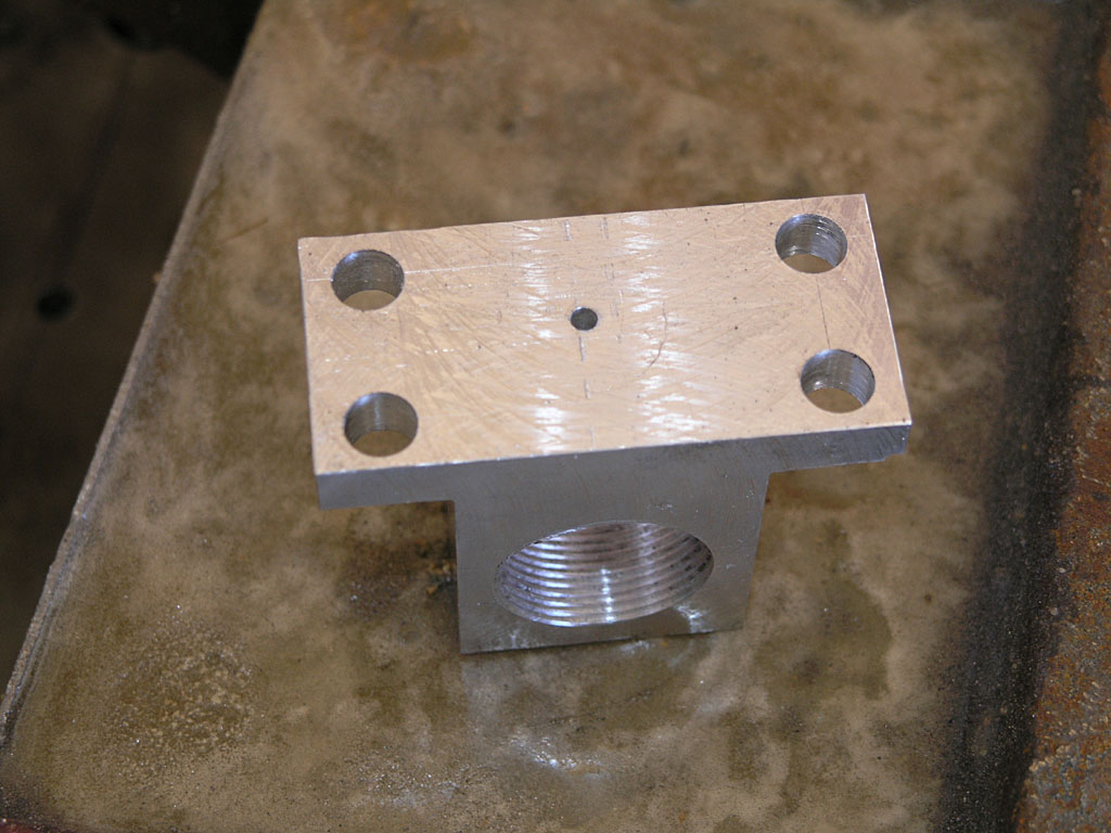
Last bit is the mounting holes. A little Dychem marking dye and the surface plate and height gage routine and I've got it marked out for dirlling...
All done!
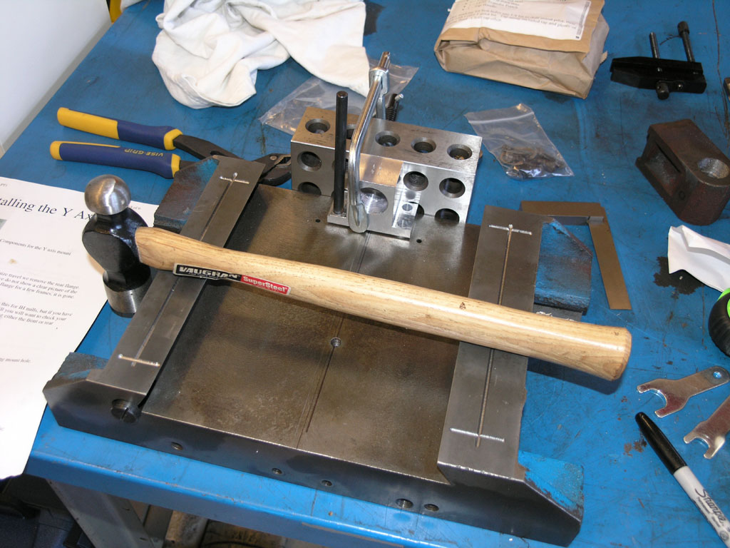
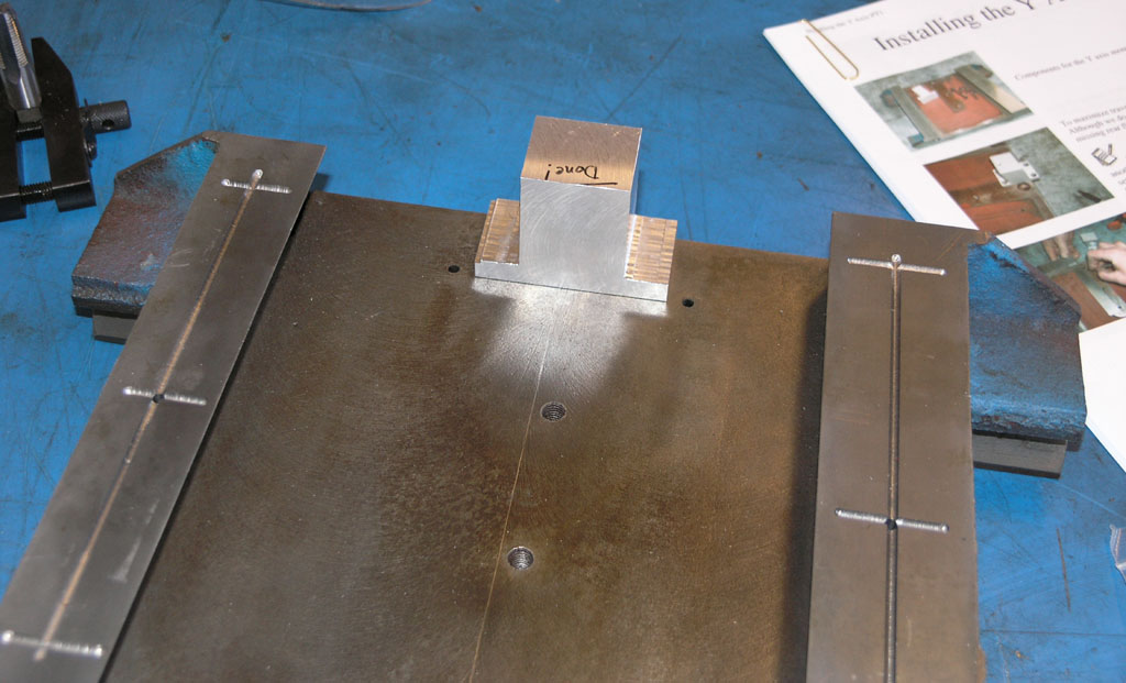
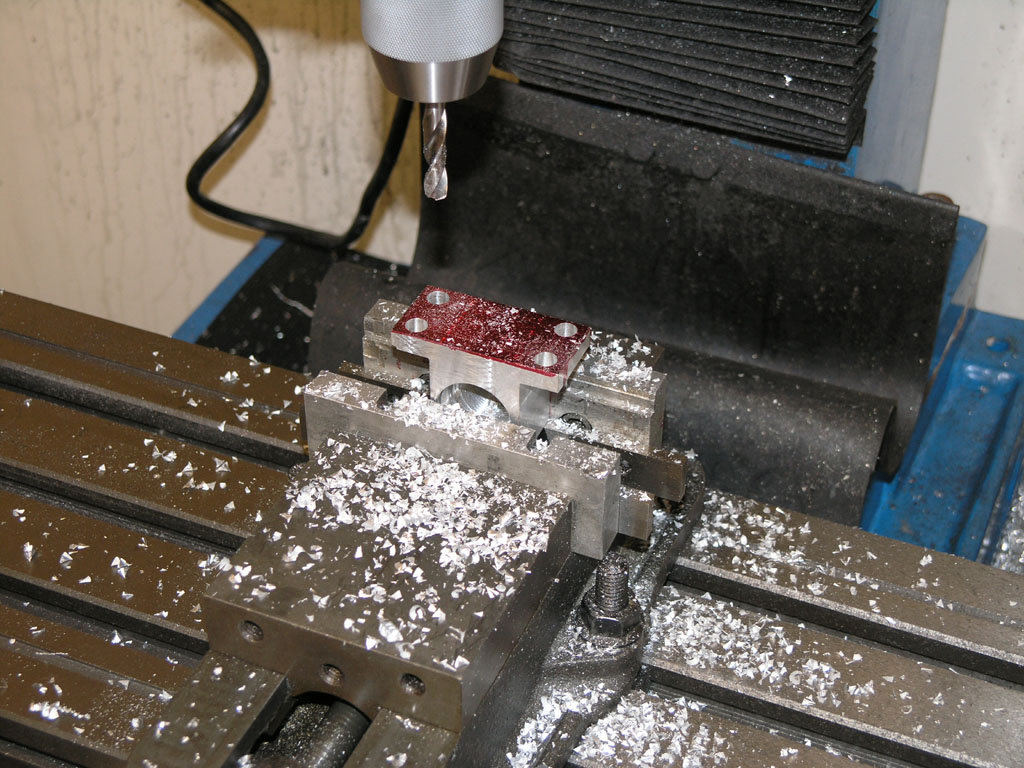
This crazy setup is being used to transfer punch the mounting holes to the saddle...
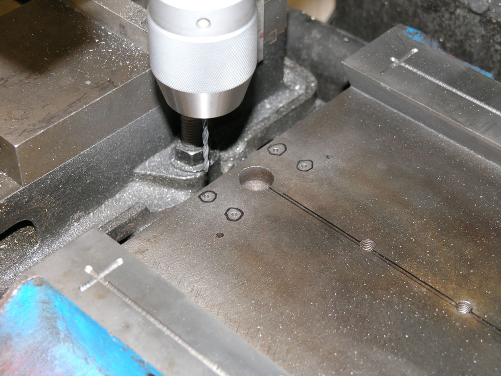
First we drill with a 1/8", then a larger bit...
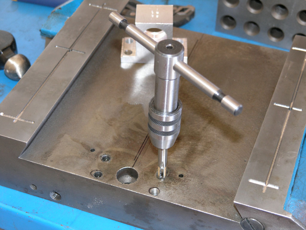
Finally we tap the holes. IH sends this nice tap wrench and some real taps instead of the "tap and die set" variety. Very nice! I think all the hardware is 5/16" 18 TPI...
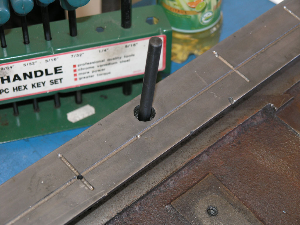
There is a hole that goes through the way right above the mounting bracket. I am transfer punching through it into the bracket...
This little 1/8" hole is at the other end of that hole through the way. It's purpose is to drip oil onto the ballscrew...
All done with that project!
|
Do you want to be a better CNC'er? Get Better Tool Life, Surface Finish, and Material Removal Rates.
|
||||||||||||||||||
| ||||||||||||||||||