|
|
|
|
|
|
|
Do you want to be a better CNC'er in 37 Seconds? Get Better Tool Life, Surface Finish, and Material Removal Rates Fast. It's that easy. You can install and get results now. |
| Safe Start Block to Swiss Lathe |
A Safe Start Block connotes a location in the part program where the program could be safely started because the programmer has provided at that point everything the program needs to know to execute correctly. You could cut and paste from a safe start block up to the next safe start block and you'd have a program segment that would run safely all by itself or as part of another part program. By convention, safe start blocks often begin with a toolchange.
The Safety Charge Pump, often just called a Charge Pump,
is a safety feature. It is basically
a signal that the software sends to the hardware that acts as a heartbeat. So long as the heartbeat is there, the hardware
knows that the CNC controller software is running, and the signals coming
from it should be acted on. If
the heartbeat disappears, it means the CNC controller software is no longer
running, and any signals from the PC should be ignored as they are likely
in error.
S-Codes are responsible for controlling speed in part
programs.
Scraping is the preferred method of ensuring flatness
with a very high degree of precision.
It is a manual task and a somewhat difficult task to learn. The bible for information on scraping is a
book called Machine Tool Reconditioning by Connelly.
Any lathe that creates parts from continuously fed bar
stock.
The number of independent turns on a screw shaft; usually
one, two, or four.
These are operations done on a separate, usually simpler
and cheaper machine, after the primary operations are completed. By using secondary operations, a manufacturing
facility can do operations in parallel on a second machine and thereby
achieve higher efficiency.
A servo
is a motor equipped with an encoder or other feedback device to create
a closed loop system (See Also Closed Loop). Theyre favored for CNC applications because
they are more precise and have higher performance than steppers. They also have a much broader torque curve.
Servo
amplifier is the name typically given to the driver used with a servo
motor. This is because the feedback (See Also Feedback
and Closed Loop) information provides a differential value (meaning the
difference between desired position and actual position) which is amplified
to change the motor speed in order to reduce the differential. This amplification is called servo gain.
A servo
fault occurs when the following error (See Also Following Error) becomes
too great and the CNC control shuts down the machine until the operator
can see whats wrong. The following
error may become too great due to a crash or simply because the machine
was being operated at feeds and speeds that were beyond its capabilities.
A parameter
in a servo system that determines how rapidly the system responds to feedback
(See Also Feedback). High servo
gains makes for a very responsive system that has high performance, but
it can also cause instability and susceptibility to noise.
Servo
systems require tuning, which is the process of setting various parameters
so that they function smoothly and with a minimum of following error (See
Also Following Error) and instability.
The most important parameter is servo gain (See Also Servo Gain).
One
parameter system is called PID (See Also PID) for Position, Integral,
and Differential. It is one of
the simpler methods of parameterizing servo systems for tuning, but it
is very effective.
The expected value that a servo system is commanded to achieve, for example an axis position.
A setup is a particular configuration of workpiece, workholding, and tooling.
A set of machining operations on the workpiece without the need
to remove it from the workholding system is
considered a single setup. Setups
generally take time and involve precision measurement and alignment, so
being able to perform a lot of operations on a single setup is advantageous
for productivity.
Shielded cable typically has foil or a braided covering
surrounding the conductors. The
foil or covering is then grounded to prevent electrical noise from entering
or leaving the cable. It is a good
practice to use shielded cable with CNC machinery to help control electrical
noise and ensure reliable operation. See
also Noise.
A mode triggered from the operator panel wherein the
program executes one block each time the Cycle Start command is issued. This makes it easier to try out the program
a single step at a time and see what it does.
Single shot oiling is a feature on machine tools whereby
a series of passages and plumbing supply lubricant to all the key points
on the machine from a single source. That
source may be a manual or automatic pump.
Use of single shot oiling is much more convenient for the operator
and assures consistent lubrication to the machine for best performance
and longest life.
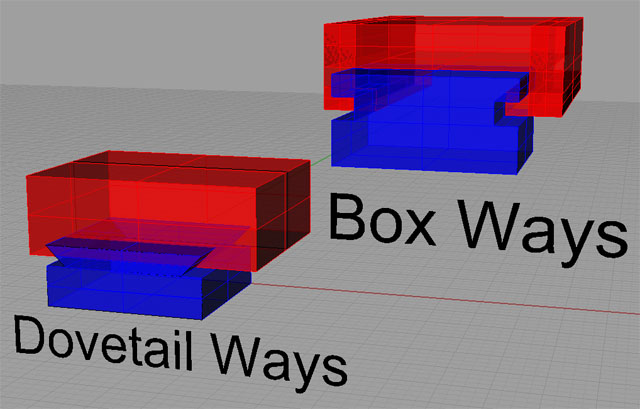
Sliding ways are used by many machine tools so that their
axes may slide against one another.
There are four prominent designs:
-
Dovetail Ways: Very
common on mills, dovetail ways look like the dovetails used in wood joinery.
-
Box Ways: Box
Ways are rectangular cross section, as opposed to the angular shape of
dovetail ways. Box ways are
very strong, but they suffer from two shortcomings.
First, they involve a lot of surface contact area, so managing
friction is key. Second, in
order to slide at all, some clearance is required, which results in some
slop in their travel. They
are the strongest and most rigid design, but they are difficult and expensive
to manufacture.
-
-
Milling a channel in the surface of
a workpiece. For best accuracy
and surface finish, a cutter narrower than the slot width can be used. Cut the middle of the slot first, and then cut
each edge so that the final finish does not require the cutter to machine
on both sides at once.
The ability of the CNC control software to set limits
on axis travel in the software. Once
set, the software should never command the axis to move beyond the limits.
A solid model refers to the abstract model a 3D CAD program
creates, or to the data in the file from such a program.
A solid model represents a 3D object.
A solid state relay is just what it sounds likea relay
with no moving parts. See Also
Relay.
Solidworks is an extremely
popular CAD program often used for CNC applications.
Some say it is the most popular software used by CNC professionals.
The spindle of a machine is the part
that rotate either the workpiece or the cutter at high speed for
machining.
Similar to Feed Override, Spindle Override lets the operator manually change the spindle speed to increase or decrease
it by a percentage of the programmed speed for fine tuning purposes.
Usually refers to a lathe spindle, although one could also be installed on a mill. These sensors are used to measure the speed and sometimes the position of the spindle. It is particularly important to understand spindle speed when threading. In that case, the sensor is telling the control program, such as Mach 3, how to keep the two axes synchronized to produce the thread.
A variety of sensor types may be used including optical
encoders, optical sensors that work by reflectance or interruption of
beam, and Hall Effect proximity sensors.
A spindle speeder or spindle increaser is an attachment for a milling machine that contains a gearbox that multiplies the speed of the spindle. This makes it possible to achieve the smaller speeds needed for smaller cutters, engraving cutters, and jig grinding.
A bed mill with a square column equipped with a dovetail
way to support the head in the z-axis.
When starting to machine stock, it is often advantageous
to begin by squaring the workpiece. This
is a process of machining all edges of a rectangular block until they
are flat and square. Doing so ensures
future machine work will be more accurate because the sides of the block
will index properly in the vise or other workholding
device.
The same can be accomplished for a lathe by taking a
light facing and turning cut to ensure a true cylinder aligned with the
axis of spindle rotation.
Squaring is the process of ensuring that the axes of
a mill are at right angles to one another.
This is accomplished by shimming, machining, or otherwise adjusting
the mating surfaces.
ISO-10303 STEP Product Data files. STEP stands for the Standard for the Exchange of Product Model Data. STEP is a standardized CAD file format using XML that is relatively new and still evolving. STEP Tools has quite a bit of information on STEP at their web site.
Step and Direction are a type of controller protocol favored for use with stepper motors although there are servo drivers from companies like Gecko that also accept step and direction inputs. Mach3 and other machine control software often emit step and direction signals over a parallel port or other communication medium.
A step is a unit of motion for a stepper motor.
The step-over is the amount of a cutters diameter that
is engaged in a cut. Typically,
the step-over should be 75-80% of the cutters diameter or less.
A stepper is a motor that moves in discrete steps. Typical motors have 200 steps per revolution, but many other specifications are available. See Also Hybrid Stepper, Bipolar, and Unipolar.
Steppers are less expensive than servos, but are generally
less desirable for high performance applications because they are usually
operated as open loop systems.
Stick slip is a phenomenon due to the fact that friction
between two moving objects is lower than between two stationary objects. The force required to make the two objects is
great enough that the objects will suddenly slip uncontrollably when they
start to move. This is a property
that machine tool designers must deal with because CNC machines start
and stop frequently and expect to do so over very short distances and
with great precision.
One of the chief steps taken to combat stick slip has
been the use of PTFE on the ways. PTFE
has nearly identical coefficients of static (fixed) and dynamic (moving)
friction. See also PTFE and Acetal.
STL is an abbreviation for "stereolithography language". It is a file format commonly used by CAD/CAM programs to represent 3D models. STL models consist exclusively of triangulated meshes, so such files may not be the most desirable form for a model as they lose information such as the original smooth curve or NURB (See Also "NURB") that was used to create the object.
A technique used in 5-axis milling where a ballnose cutter
is operated at an angle other than vertical to the surface to that the
dead spot on the end of the endmill that's hardly moving is not used.
If you look at a ballnose cutter, the effective cutting speed reduces
the closer you get to the tip until it is theoretically zero right on
the tip. It is possible to utilize Sturz milling without a 5-axis machine
so long as the orientation of the workpiece is such that the dead tip
of the cutter is not engaged in the workpiece..
Surface speed, sometimes called Cutting Speed, is a measure
of how fast the tool is moving over the work as it cuts. It is measured in SFM or Surface Feet Per Minute. Ideal surface
speeds vary by material and are categorized in Machinerys Handbook.
Some typical values (look up the correct ones, these are for illustration!)
might be 500 for plastic, 300 for aluminum, 200 for brass, 100 for mild
steel, and 50 for stainless steel.
A lathe whereby the work is fed through
the spindle to provide Z-axis motion--the tooling does not move in Z. Most lathes keep the workpiece fixed and only
the tool moves in relation to the rotating workpiece. Swiss lathes excel at creating complex small
cylindrical parts.
| Safe Start Block to Swiss Lathe |
|
Do you want to be a better CNC'er in 37 Seconds? Get Better Tool Life, Surface Finish, and Material Removal Rates Fast. It's that easy. You can install and get results now.

|
||||||||||||||||||
| ||||||||||||||||||