|
|
|
|
|
|
GD&T Tutorial Home GD&T Symbols
CNCCookbook Beginner's Guide to GD&T: Symbols
Geometric Dimensioning and Tolerancing (GD&T) Symbol Quick Reference
Control Type
|
Characteristic | Symbol | Notes |
| Form | Flatness |  |
Controls form (shape) of size and non-size features. Datum reference is not allowed |
| Straightness |  |
||
| Circularity (Roundness) |  |
Controls form (shape) of size features only. Datum reference is not allowed |
|
| Cylindricity |  |
||
Orientation No relation between features |
Perpendicularity | 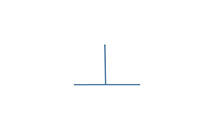 |
Controls orientation (tilt) of surfaces, axes, or median planes for size and non-size features. Datum reference required. Optional: Angularity symbol may be used for all orientation controls. |
| Parallelism |  |
||
| Angularity | 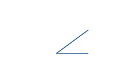 |
||
Location |
Position |  |
Locates center points, axes and median planes for size features. Can also control orientation. |
| Profile of a Surface | 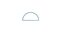 |
Locates surfaces. Can also be used to control size, form, and orientation basaed on datum reference. |
|
| Profile of a Line |  |
||
| Runout | Total Runout | 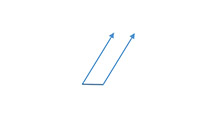 |
Controls surface coaxiality Can also control form and orientation of surfaces |
| Circular Runout | 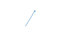 |
||
| Location of derived median points. | Concentricity |  |
Locates derived median points of a feature Not common, consider position, runout, or profile instead |
| Symmetry | 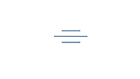 |
Feature Control Frame Modifiers
Symbol |
Modifier |
Notes |
Free State |
Only applies if part is otherwise restrained. | |
Least Material Condition (LMC) |
Useful to maintain minimum wall thickness | |
Maximum Material Condition (MMC) |
Provides bonus tolerance only for a feature of size | |
Projected Tolerance Zone |
Useful on threaded holes for long studs | |
Regardless of Feature Size (RFS) |
Not part of the 1994 standard | |
Tangent Plane |
Useful for interfaces where form is not required | |
Unilateral |
Appears in the 2009 version and refers to unequal profile distribution |
These symbols are provided as a reference for CNCCookbook's free GD&T Tutorial. To learn what they mean, read on or check the Table of Contents for more information.


|
Do you want to be a better CNC'er in 37 Seconds? Get Better Tool Life, Surface Finish, and Material Removal Rates Fast. It's that easy. You can install and get results in a matter of minutes.
|
||||||||||||||||||
| ||||||||||||||||||