|
|
|
|
|
|
|
Do you want to be a better CNC'er in 37 Seconds? Get Better Tool Life, Surface Finish, and Material Removal Rates Fast. It's that easy. You can install and get results now. |
Belt Drive for the Industrial Hobbies/Rong Fu Mill
Part 2: Construction Planning
Spindle Drive Adapter
The critical and most difficult part to fabricate for the IH belt drive is the Spindle Drive Adapter. This piece has to fit over the top splined part of the spindle to drive it. It must do so tightly, while transferring the full power, and it must be supported in bearings so as not to allow the tension on the belts to transfer lateral force onto the spindle itself.
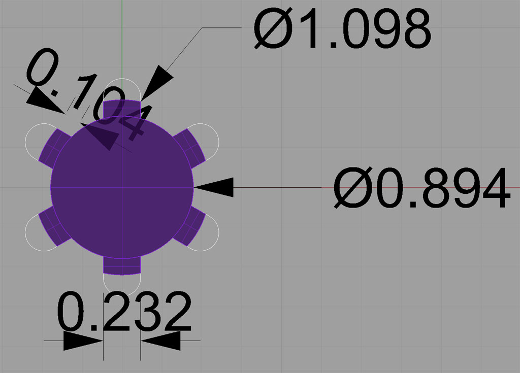
Here are the dimensions for the Industrial Hobbies mill spline:
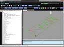
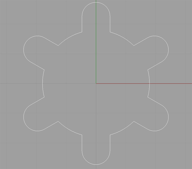
Rather than broaching the splined piece, I plan to just mill out an approximate shape, something like this:
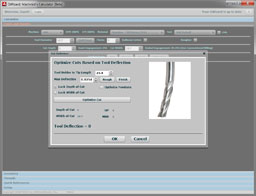
This path can be milled out via CNC using a 3/16" endmill. I want this part of the adapter to be at least 1" thick so it is solidly clamped to the spindle. That's apt to be a chattery business to cut more than 5x deeper than the endmill diameter, so I plan to drill 6 holes and then interpolate the center hole (or perhaps bore it in the lathe) before I attempt to profile the complex curve. The spline width of 0.232 is a touchy business too, since it is smaller than 1/4" and much larger than 3/16", finding an appropriate endmill diameter is problematic. If I can use a 6mm diameter endmill, that gets me with an oversize of 0.004". Worth a try to see if it works very well being that much oversize.
Rather than profile those deep slots to connect the interpolated center hole with the drilled spline holes, I am thinking the answer is some plunge milling. Plunge milling is ideal for rigidity challenged situations. In this case, a series of plunges that move from the center hole radially to the drill holes should clear out that material very nicely without a lot of chatter.
I'll machine a test piece that consists strictly of this part to trial fit it to the spindle shaft before I attempt to make the overall adapter. I want to make sure it all comes off well!
CNC Codes
Note: These codes are for a test piece, and not the actual adapter!
Spline Holes: Drill 6 holes with a 0.236" twist drill bit ("A" drill).
Center Hole: Interpolate the center hole with a 1/2" 2 flute endmill.
Final Profile: Cut the final profile with a 3/16" (0.1875") endmill.
Sheave Designs
A little research in Gates Heavy Duty V-Belt Design Handbook yields their recommended minimum sheave sizes. I am still waffling on a 1750 rpm vs a 3450 rpm motor, so I picked a minimum size a tad larger than what the 3450 requires. These minimum sizes are designed to allow maximum transmission of power--in this case up to 5 HP. Allowing for a 2:1 ratio at either end (e.g. my 1750 rpm motor will drive the spindle to 875 rpm or 3500 rpm depending on which ratio is selected, hi or low), I want a 2.75" small sheave and a 5.5" large sheave.
I have settled on using a K-series multi-rib belt because what the heck, that's what Fadal used for their spindles. It's probably overkill, but the belts are cheap. Getting the K-series profile right was not hard given a G-Wizard user had just sent me some information machining sheaves for automotive ribbed belts. Here is the K-Series profile:
For "K" series belts (most automotive belts) : P = 0.140" (3.56mm), W = No. of Ribs X P, T = 0.235" (5.97mm), H = 0.110" (2.79mm), A = 40 deg.
For "L" series belts: P = 0.185" (4.70mm), W = No. of Ribs X P, T = 0.280" (7.11mm), H = 01.65" (4.19mm), A = 40 deg.
I need to think a little more on whether to stick with the K or drop down to say a J-series to reduce the size, but for now, let's continue the exercise assuming K-series. Here is what the double sheave will look like:
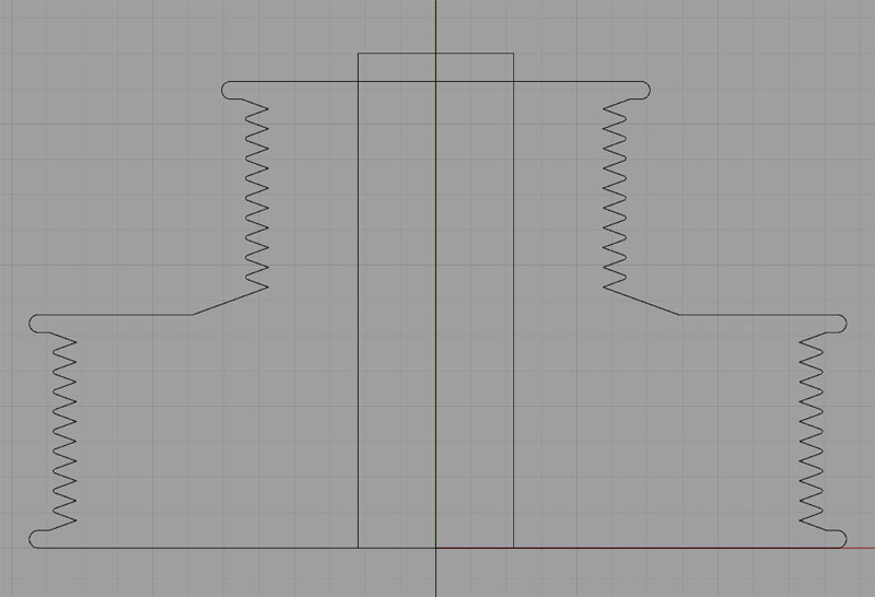
A rough profile of the double sheave...
There's still some design features to think about:
- How will the sheave be locked in place on the spline?
- How about guaranteeing the height of the bottom above the base so there is no rubbing?
- What about a speedometer or encoder provision?
The grooves for the belt ribs are 40 degree angle. I also need to think about what sort of tool I want to use to machine those:
- The automotive ribbed belt tooling from Tool-Flo came well recommended, so I need to see what that would cost.
- The grooves can be profile with a 35 degree diamond tool. A combination of SECO VCGT331F-AL KX insert in a SVVBN123 holder was recommended in this Practical Machinist thread.
- I can also grind a 60 degree threading insert to the 40 degrees required for these sheaves.
A number of considerations here. The Tool-Flo and reground threading inserts are all about plunge grooving while the 35 degree diamond is all about profiling. Plunge grooving would be very easy to hand program if your CAM doesn't support it, but most any CAM will figure the profile needed by the 35 degree diamond. If you had to make a bunch of pulleys (I don't), it might be better to plunge groove.
|
Do you want to be a better CNC'er in 37 Seconds? Get Better Tool Life, Surface Finish, and Material Removal Rates Fast. It's that easy. You can install and get results now.

|
||||||||||||||||||
| ||||||||||||||||||