|
|
|
|
|
|
|
Do you want to be a better CNC'er in 37 Seconds? Get Better Tool Life, Surface Finish, and Material Removal Rates Fast. It's that easy. You can install and get results now. |
| 2.5D to Brushless DC Motor |
2.5D refers to a machining scenario in which there are
no overhanging elements to the part. In
other words, everything that must be reached can be reached by plunging
straight down from above.
Refers to a machine or CNC scenario
that has 3 axes of motion available, usually X, Y, and Z.
3DM is the file extension for a Rhino 3D CAD file.
Refers to a scenario or machine in which 4-axes of motion are available. Usually these are X, Y, Z, and a 4th rotational axis. The 4th axis is typically the ability to rotate along an axis normally parallel to the X-axis, and is usually referred to as the A axis.
This capability is extremely useful for a lot of situations. For example, it allows machining features onto a curved surface, such as a shaft or cylinder, as the shaft or cylinder is rotated in the 4th axis. It can also allow access to the underside of a part or direct access to the sides without having to manually flip the part to another orientation.
5 Axis CNC adds a second rotational axis to the X, Y, Z, and A axes for even greater flexibility.
Programming a 4 axis system can be more complex, and a 5 axis system is extremely complex to program.
See also "Axes", 4th Axis and
5 Axis CNC.
The term 4th Axis often refers to the hardware
necessary to add a 4th axis to a 3 axis CNC machine. This hardware typically consists of a motorized
rotary table mounted on the machines table and aligned so its axis is
congruent with the x-axis of the machine.
5-Axis CNC is generally a mill or router that has an X, Y, and Z-axis working perpendicular to one another together with two rotating axes. Imagine a 4th axis rotating table that is used to rotate a 5th axis that can also rotate at right angles to the 4th axis.
This configuration provides the maximum machining flexibility in a single setup of any of the CNC configurations. Certain types of applications almost require 5-axis machining to be successful. For example, cylinder head porting requires the milling cutter to reach inside a convoluted intake or exhaust port in a cylinder head, a task that would be just about impossible to do in more conventional configurations.
5-axis machines are generally quite expensive and difficult
to program, however.
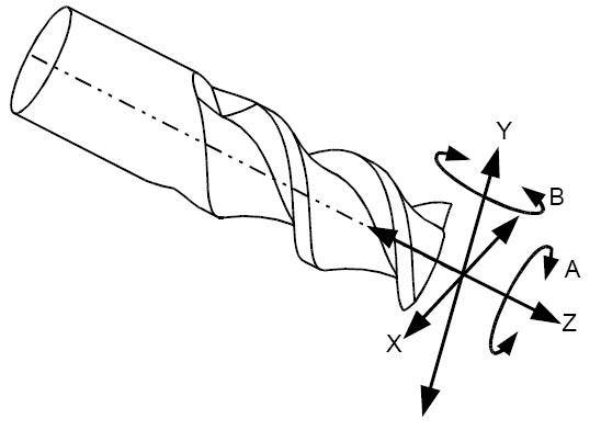
The A-Axis is the rotational axis about the X-Axis.
ABEC is the abbreviation for Annular Bearing Engineering
Council. It is a term commonly
used in conjunction with rating bearing tolerances or precision. A number follows the ABEC designation, and the
higher the number, the more precise the bearing. An ABEC 7 bearing is an excellent machine tool
grade bearing.
The ABEC system relates to other bearing precision rating
systems as follows:
|
ABEC SYSTEM |
|
ISO SYSTEM |
|
DIN SYSTEM |
|
ABEC 1 |
|
|
|
P0 |
|
ABEC 3 |
|
Class 6 |
|
P6 |
|
ABEC 5 |
|
Class 5 |
|
P5 |
|
ABEC 7 |
|
Class 4 |
|
P4 |
|
ABEC 9 |
|
Class 2 |
|
P2 |
Absolute coordinates are expressed relative to a fixed
position whereas Relative Coordinates (see also) are relative to the current
position of the cutting tool. The
G90 command places the part program into absolute coordinate mode. G91 cancels absolute coordinate mode and places
the part program into relative coordinate mode.
An absolute move is made using absolute coordinates,
so it commands motion to an exact location specified relative to the origin
of the coordinate system. A relative
move is made using relative coordinates and so is specified as a move
from the current position
Accuracy is the difference between the expected value
and the actual value of some measurement.
When combined with PTFE (Teflon), acetal
makes an excellent low friction material with which to coat machine ways. This is the material used on the Tormach CNC mill, for example. Rulon and Turcite are all trade names for the
PTFE + Acetal combination.
ACME is the most common type of leadscrew found in machine tool applications. The ACME thread is a particular type of thread. Compared to a ballscrew (see also Ballscrew), ACME leadscrews have very high friction and backlash, both of which are undesirable attributes for high performance CNC applications.
On the other hand, ACME leadscrews can be made to very
high precision, and they are often cheaper than ballscrews. They are almost universally the choice for manual
machines.
The terms "Active High" and "Active Low"
refer to how electrical signals are interpreted. In Active High logic,
the presence of a higher voltage (within a specified range) indicates
a signal is present.
Angular Contact Bearings are ball bearings designed to
deal with heavier axial loads. A typical ball bearing is designed to deal with pure radial loads
and are not well supported the closer the load comes to the axis
of the bearing. They are commonly
used to support leadscrews and in building precision spindles for machine
tools.
There is a complex system of standardized nomenclature used to identify the characteristics of an AC Bearing from the part number. For example, AC Bearings have a contact angle that determines how far off axis they are supported for loads, they have a precision (See also ABEC), the have preload specifications (See also Preload), they have dimensional characteristics in terms of their bore, outer diameter, etc., and they have ratings that relate to their maximum operating speeds in RPM.
The best place to learn more about angular contact bearings is from the manufacturer's bearing catalogs:
An arbor can be either a workholding device, or a toolholder. As a workholder, it generally refers to a device that can expand it's OD to clamp the ID of a workpiece. As a toolholder, it is similar to a spindle and is used in conjunction with grinding and buffing. A very similar term is "Mandrel".
ASE is the file extension for 3DS Max ASCII export files from Autodesk. In other words, a CAD file.
See Also Toolchanger.
A CNC machining center that does grinding. Most automatic grinding centers are used to grind and sharpen tools and inserts.
See also Machining Center.
Following are diagrams depicting the basic axes for mills and lathes:
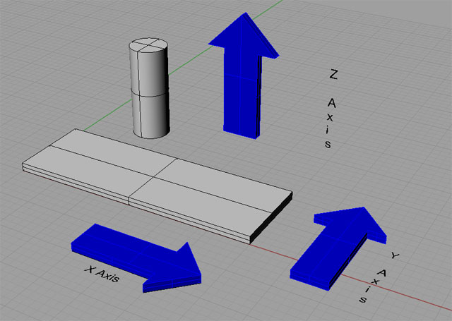
Mill Axes
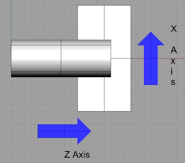
Lathe Axes
On a 4-axis or 5-axis mill there are additional rotational axes. Here is an example of a 5-axis mill with trunion table:
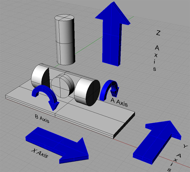
5-Axis Mill With Trunion Table
A 4-Axis Mill simply omits the B-Axis.
Back Driving is the tendency a ballscrew (or any leadscrew really) can have to spin when a force is applied to the nut along an axis. Because they are such inherently low friction devices, it becomes possible for the cutting force of the machine to back drive the ballscrew and move the table unless a force is provided to prevent that.
This is one reason why manual operation of ballscrew equipped machines may not be possible unless the machine is carefully designed to prevent back driving either by careful selection of the ballscrew pitch or fitting of an adjustable friction device to hold the axis in place by preventing the ballscrew from turning.
In CNC applications, the stepper or servo drive locks
the ballscrew in place so there is no problem with back driving.
In some cases, it may be possible for a heavy vertical load to
backdrive downward due to its weight after the
machine is turned off.
When a step motor or servo motor is decelerated, it generates
Back EMF. In essence, it will
try to pump electricity back into the power supply. This can be destructive to the components in
the worst case, as that electricity must find somewhere to go. In a system where multiple motors share the
same power supply, it may be that another motor can use the electricity. Alternately, a capacitor in the power supply
may be able to absorb and buffer the Back EMF.
Some power supplies employ specific circuitry to deal with the
Back EMF.
Backlash is any kind of unexpected play in an axis due to clearance or looseness of mechanical parts. When the axis is commanded to move, the drive motor may turn briefly before movement begins. That delay is the backlash.
Backlash has a variety of causes. The most common is play between the leadscrew threads and those of the nut. ACME screws can have considerable backlash of this kind, while ballscrews may have almost none. Another source is any tendency for the screw to move axial in the bearings that hold it, or any other such play in the system. Precision angular contact bearings with preload are often used to combat this tendency. Gears, belts, and chains can all introduce backlash into a mechanical system. Even loose fasteners or flex in the mounting plates or chassis can be a source of backlash.
In some cases, backlash can be compensated for in the
driving software using a feature called Backlash Compensation (see Backlash
Compensation).
Backlash compensation is a feature of the software used
to control the drive motors of a CNC system.
By telling the software how much backlash exists in the system,
it will try to compensate for that backlash.
It does this in a manner similar to the way manual machinists do. Namely, the software expects that when an axis
reverses direction, it will not move until the backlash has been taken
up.
Backlash compensation is a useful feature, but it is
no panacea or excuse not to try to eliminate all backlash
from a CNC system. Sometimes, an
axis needs to smoothly change direction without waiting for the backlash
to catch up. The classic example
is when machining a circle, where the direction changes multiple times. Backlash compensation will not eliminate errors
in machining the circle.
A device that may be added to a leadscrew to reduce or eliminate backlash. Backlash eliminators were sold or provided as a feature of machines that did not have ballscrews in order to control backlash and enable climb milling. A backlash eliminator could be as simple as a double nut setup with a precision spacer between the nuts to eliminate the backlash on an ACME leadscrew. The term is less prevalent in more recent times as ballscrews have become common on machine tools.
See Also ACME, Backlash, and Climb Milling.
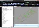
Backplotting is a feature of CAM programs whereby the path followed by the tool can be backplotted onto the drawing. A backplot typically shows all the passes at once. Here is a typical backplot from OneCNC Turn for lathes:
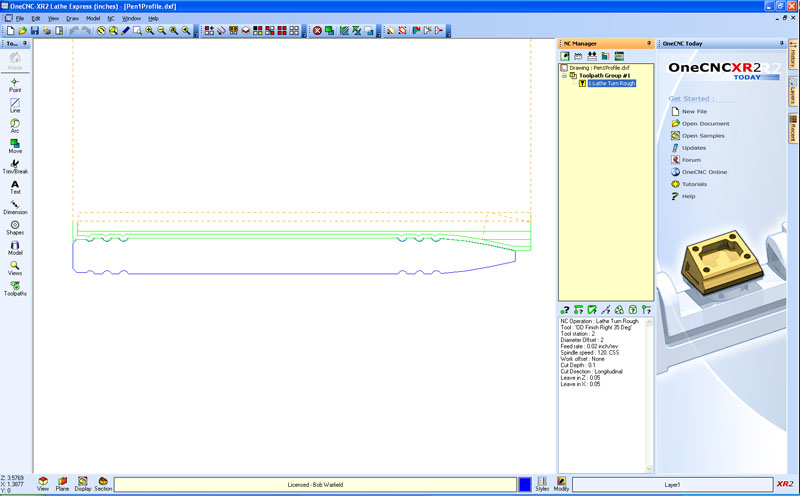
A backplot: green lines are cuts, dotted red are retracts between passes...
Ball mills are end mills that have a half spherical bottom.
Theyre favored for 3D profiling because they dont have a flat
bottom. They have some unique cutting
problems at the bottom because the relative speed varies all along the
ball. The cutter is moving fast
out at the diameter of the ball than it is at the center when viewed along
the axis.
The ballnut is the nut component
that is paired with a ballscrew. Theyre filled with ball bearings, and have
connecting passages that recirculate the ball
bearings back to the top of the nut after the roll over the threads of
the ballscrew all the way to the bottom.
Ballnuts may be preloaded to
reduce backlash either by using oversized ball bearings in them to take
up the slack, or by using them in pairs with tension or preload between
the two nuts.
They are are typically mounted
to the machine tool using either a flange or a thread on the nut. They must be lubricated and protected from chips
and other debris.
Ballscrews are highly efficient low friction and low backlash leadscrew devices that use ball bearings rolling in a channel cut into the screw. The low friction and backlash attributes are extremely valuable for precision CNC applications where they are used to drive the axes of the machine.
Ballscrews come in rolled and ground types, with the
latter being more accurate, having lower backlash, but also being quite
a bit more expensive than rolled ballscrews.
Ballscrew Mapping is a software feature of the CNC control
software (such as Mach 3) wherein a map of the errors in the ballscrew is entered and the software attempts to automatically
compensate for these errors. The
errors are expressed in terms of how far off from the desired position
the screw is at various distances along the screw.
Ballscrew mapping can be a very effective way to increase
accuracy in the machine, but it requires extremely accurate methods to
measure the true position of the axis along the length of the screw. This is typically done using gage blocks and
a dial indicator or even better by using linear scales and a DRO. The most precise method of calibrating a ballscrew map is laser interferometry.
Bar Feeders and Pullers are devices used to automate
a continuous feed of bar stock to a lathe so that the operator doesnt
have to keep loading new stock as parts are made.
The B-Axis is the rotational axis about the Y-Axis.
A bed mill, sometimes called a column mill, is the most
common way to construct a vertical CNC mill.
In this design, the spindle is affixed to a vertical column and
slides on ways up and down the column.
Bellows are used to protect the ways and leadscrews on
a machine from chips and coolant.
Belt drives may be used in machine tools to connect a drive motor to an axis leadscrew, or to connect the motor to the spindle. They can even do double duty as a replacement for the leadscrew on a plasma or router table when the belt runs the entire length of the axis and the axis is attached to the belt at one point.
Common types of belts include Timing Belts (See also
Timing Belts) and V-Belts. Timing
belts will generally present lower backlash and be a more efficient, so
V-Belts are primarily used for motor to spindle cases.
Even there, a timing belt may be preferable.
Step motors are typically 4, 6, or 8 wire devices. Bipolars
have no center taps, so if there are only 4 connections, the motor is
a bipolar only design.
A block is the smallest operational unit of a G-Code part program. Think of it as a single statement of code, or a single operation that the machine could perform. In printed form, a block is a line of text.
A block consists of:
1. An optional delete character: /
2. An optional line number
3. Any number of segments, where a segment is a word or comment
4. An end of line character
The execution of segments within a block will be the same regardless of their order. This can be a bit confusing to read, so it is often good practice to order them in a way that makes it clear what should happen.
Blocks ignore whitespaces, which can also make for some confusing formatting. Blocks are also case insensitive.
There are some further limitations on the number and
type of words that can appear in a block depending on their interactions
with one another.
If the block delete control is on, lines of code which
start with a slash (/) are not executed.
In a drawing, a bounding box is the smallest rectangular space aligned with the axes of the coordinate system that would completely contain the object and with no extra room to spare. It is a useful way to gain a crude understanding of the overall dimensions of a thing, perhaps so that an appropriate piece of stock could be chosen from which to make it.
A box tool is an integrated follow rest and cutting tool combination designed for use where it may not be possible to employ a tailstock to help support the workpiece:
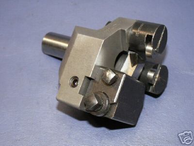
Box Tool...
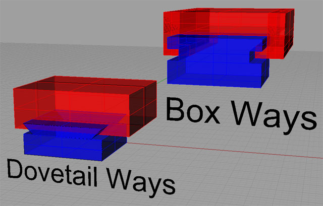
Sliding ways are used by many machine tools so that their
axes may slide against one another. There
are four prominent designs:
-
Dovetail Ways: Very
common on mills, dovetail ways look like the dovetails used in wood joinery.
-
Box Ways: Box Ways
are rectangular cross section, as opposed to the angular shape of dovetail
ways. Box ways are very strong,
but they suffer from two shortcomings.
First, they involve a lot of surface contact area, so managing
friction is key. Second, in order
to slide at all, some clearance is required, which results in some slop
in their travel. They are the strongest
and most rigid design, but they are difficult and expensive to manufacture.
-
-
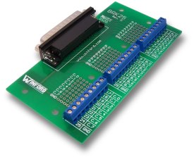
Breakout boards are generically boards designed to take
signals that come in on a particular cable or protocol and break them
out to individual connections for point to point wiring purposes.
In CNC terms, the most common breakout board is a parallel breakout board, which is used to take a parallel printer connection from a PC and break it out to individual I/O signals that may then be wired to relays, Gecko drivers, and the like.
Usually a breakout board will incorporate opto isolators (See also Opto Isolator) so that anything that happens on the point
to point wiring is isolated and cannot get back to the PC. So for example, if a high powered line was inadvertently
connected to the breakout board, the opto isolator
would protect the PC from damage, potentially at the cost of burning out
the opto, which is a cheap part to replace. Opto isolators also
eliminate the need for common grounds and create greater noise immunity.
Bridge rectifiers are full wave rectifiers, meaning
they convert the negative going portion of the AC signal to fill in the
gaps with a positive way between the normal positives in the AC. They do this using diodes in a bridge configuration
that effectively reverse the polarity on the AC signal for the negative
going portion so that it becomes positive.
Theyre typically a component of the DC or Linear Power
Supply (see also Linear Power Supply) used to power DC stepper and servo
motors. Bridge Rectifiers are robust,
relatively inexpensive solid state devices with 4 terminals. Two terminals are for the AC, and 2 are for
the DC that comes out of the device. A
capacitor (See Capacitor) is used to smooth the ripple left over in the
process.
Brushless DC motors use
a permanent magnet rotor and coils in the stator. The stator coil currents
are sequenced by an external motor controller. This eliminates noise caused
by the arcing of the brushes and greatly improves motor life, and therefore
reliability of the motor.
| 2.5D to Brushless DC Motor |
|
Do you want to be a better CNC'er in 37 Seconds? Get Better Tool Life, Surface Finish, and Material Removal Rates Fast. It's that easy. You can install and get results now.

|
||||||||||||||||||
| ||||||||||||||||||