|
|
|
|
|
|
|
Do you want to be a better CNC'er in 37 Seconds? Get Better Tool Life, Surface Finish, and Material Removal Rates Fast. It's that easy. You can install and get results now. |
Coolant Misting System for the IH Mill
Once you CNC a mill, applying coolant by hand and blowing away chips manually gets old in a hurry. Time to build a misting system for my mill.
As always, I started by researching approaches taken by others. You can see my notes on that at the bottom of this article.
Here is the finished mister (truly a horrendously bad picture, sorry!):
Spindle Ring Mounting System
I'm going to re-use the ring that came with the mill that's used to connect the depth gage. The mister was designed to look something like this:
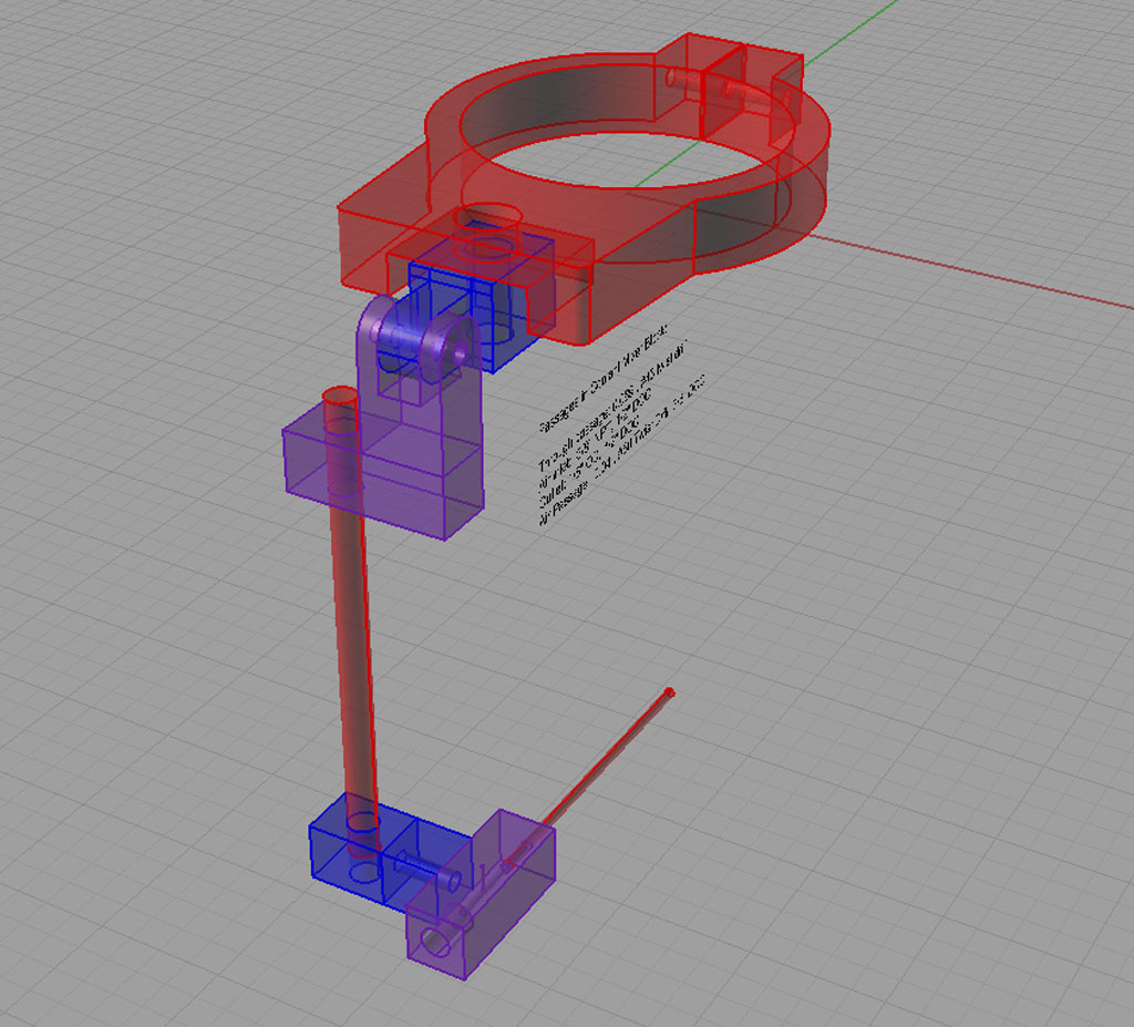
There are several ranges of motion: The knuckle on the quill ring, the sliding red bar, and the rotating mount for the mister's mixing block...
In the end of the day, I got impatient. I made the knuckle mounting and used it to mount a Noga mister that I got for cheap on eBay!
Knuckle Joint at the Top of the Mister
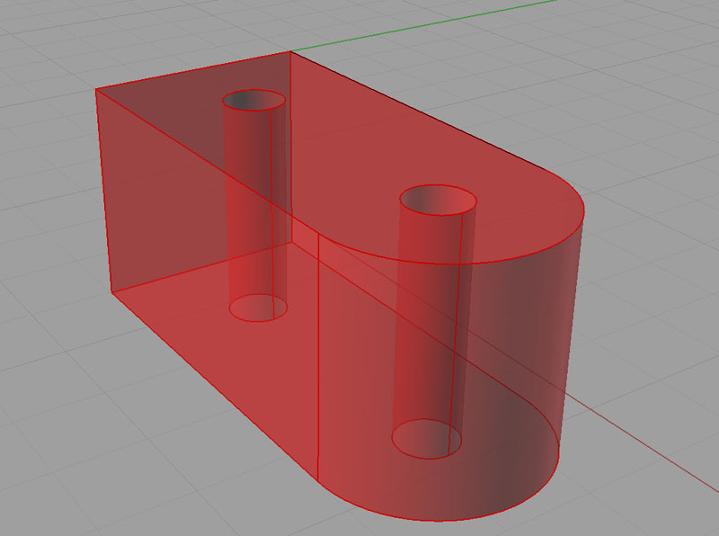
Perspective view of a rough knucle joint...
Profile for the Quill Mounting Blocks. 2 will be needed to make the knuckle joint...
I start out with some 1" x 1" steel stock. I'll cut three lengths a little more than 2.25" long for the two halves of the knuckle joint and the third is for a little fixture. The longer we make the workpiece, the more waste, but the less precision we need to locate x=0, y=0 which is the center of the hole in the square end and our reference for this work.
We'll use 2 holes through the workpieces to hold them so we can do the profiling job in one step and reach the full height. I'll just use a couple of 1/4" socket head cap screws to attach the workpiece. So, after cutting the pieces from larger stock, the first step is to make the little fixture I'll put in my Kurt vise to hold the workpiece. It's just some squared stock with threaded holes to accept the 1/4" SHCS bolts holding the workpiece. While I am squaring stock, I may as well square enough for the fixture as well as the 2 workpieces. That means I want a length that is 3 x 2.25" long = 6.75". Leaving a little room for waste, 7" or so should do it, cut into 3 roughly equal lengths.
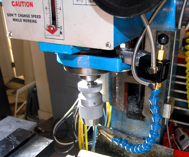
Squaring the stock is done with my 3" facemill. I'm just squaring the top and bottom faces since the sides will be completely edge milled by the profiling g-code.
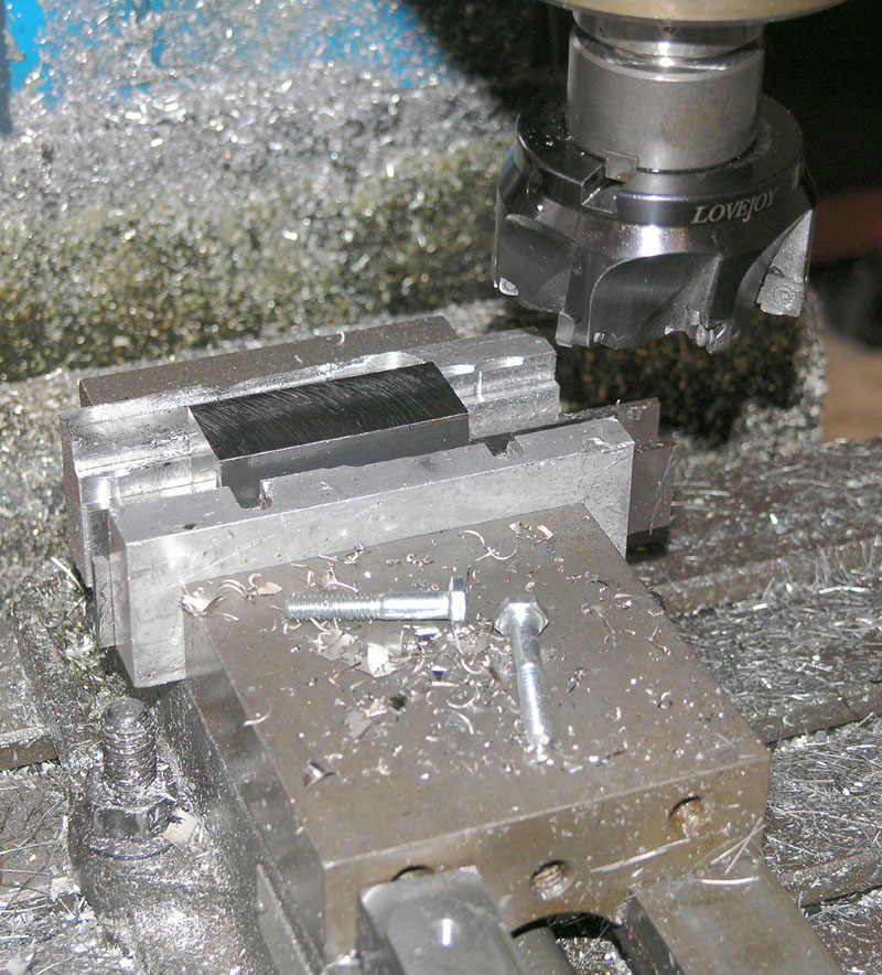
Squaring the faces on the stock with my 3" face mill...
Having squared the stock and cut it into 3 2.25" long pieces, I drill and tap the holes for the fixture. I can use the same g-code to drill each piece for 2 holes, I just need to be sure I use a vise stop so each piece is located the same and I will want a different sized twist drill for the workpieces versus the fixture. The workpieces are not tapped, so I'll use an "I" drill. The recommended twist drill for tapping the 1/4" 20 TPI coarse thread holes is a #7, which is 0.201" in diameter. The CNC doesn't know or care what size twist drill is in the chuck, I just need to set it up that way.
G-Code to drill 2 holes. This program assume z=0 at material top, and x=0, y=0 at the center of the hole on the square end.
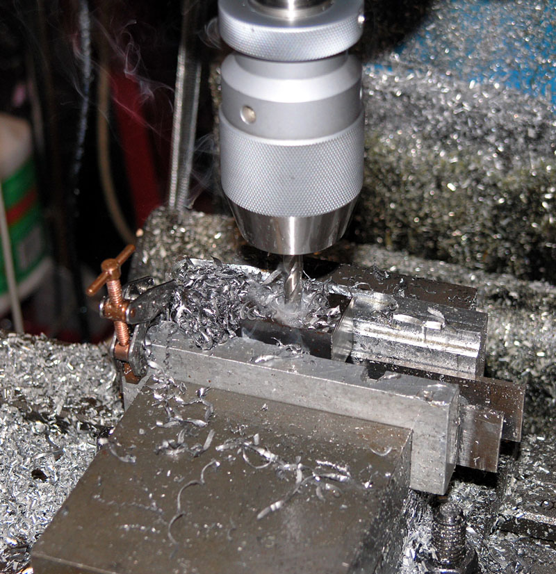
Here we are drilling the holes that will be tapped for 1/4" bolts on the fixture. I drilled through holes on the 2 workpieces...
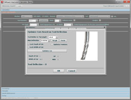
OK, having made my fixture and two workpiece blanks, it's time to profile the workpieces. From a CNC standpoint, I plan to use a 4 flute 1/2" OD endmill. I'm going to run a very light depth of cut so I can take advantage of higher feedrates of about 35 IPM at a radial DOC of 0.015". The higher feedrate is possible due to chip thinning. I've written a handy calculator that helps me determine these adjusted feedrates. The calculator also suggests 800 rpm for mild steel. My axial DOC will be a full cutter diameter or 0.500" so as to use as much of the sharp cutting flutes as possible. These parameters are pretty standard High Speed Machining practice.
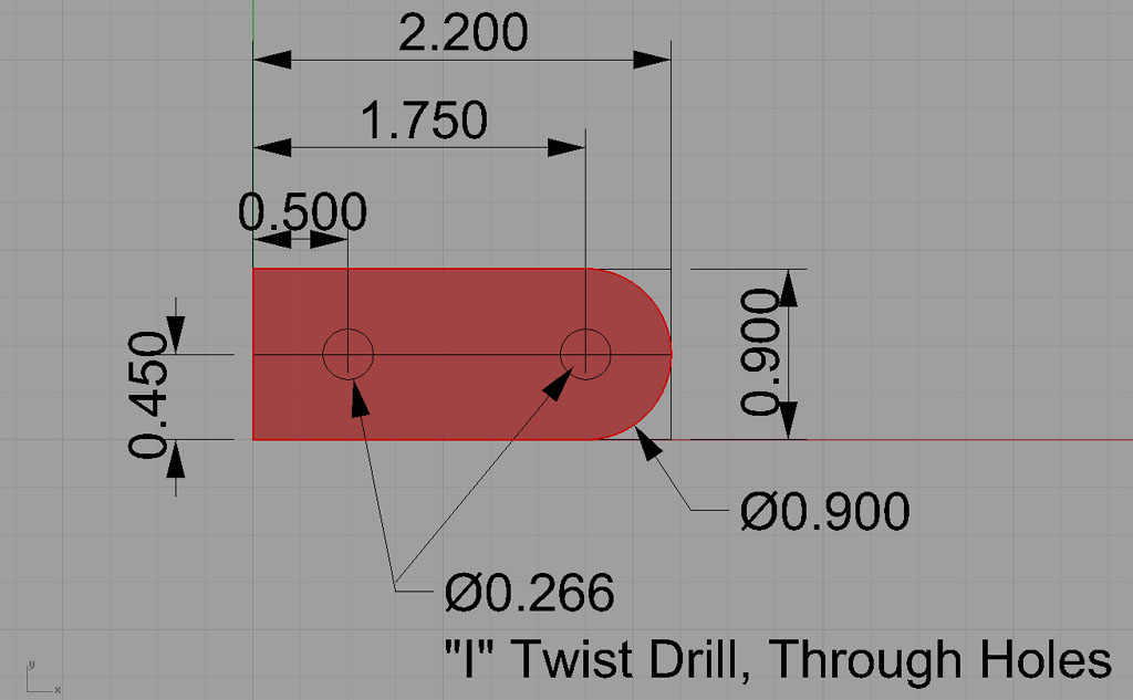
I'll define X=0, Y=0, and Z=0 as being the top of the workpiece, center of the hole in the square end. Here is a drawing that shows how the finished part will sit relative to the raw workpiece:
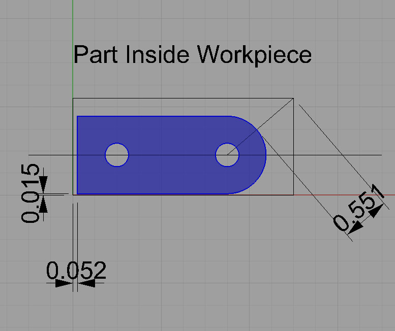
The diagonal 0.551" offset is so I could figure how far out from the material to start machining so the cutter didn't crash into the corner on its way around. The cutter is just going to follow the profile moving successively closer each pass.
Why isn't the part centered in the workpiece? That's my issue. When I set up the workpiece for drilling I was off with my edge finder (calculated the adjustment for the tip radius backwards) on one of the workpieces. Mistakes do happen. No harm is done, it just doesn't look as pretty in the rough! The G-code programs are set up for this worst case. If the part is centered in the workpiece (because the holes are centered), then the profile g-code will simply cut a little more air before it reaches the workpiece.
Profile G-Code (Click to download)
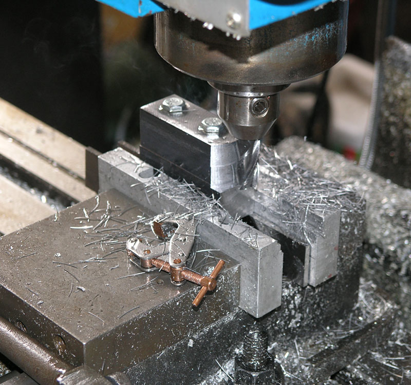
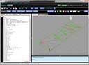
Profiling was done with 2 depths, each a full endmill diameter thick...
Have you ever seen a bench mill cutting steel at 30 IPM? Well here is my Industrial Hobbies loving it:
Being able to make cuts like that is one reason I wrote my G-Wizard Machinist's Calculator!
Finishing the Male Knuckle
Two operations are necessary to finish the male knuckle once the basic profiling is done.
First, I need to flip it so the curved profile is vertical and drill the large hole that will be used to attach it to the spindle quill clamp. I want to use a 1/2" bolt, so I'll use a twist drill for a hole that is 17/32" in diameter. The position is not critical, so I'll just eyeball to close enough and then run a Mach3 peck drilling wizard to make the hole.
Second, I need to place the workpiece in the vise so the curve end lays flat and I can relieve the curved area so the female knuckle fits properly over it. I basically want to take down the material to leave a 1/4" thick male knuckle, so I'll need to surface an equal amount from either side of the workpiece. Since I want to flip the workpiece, I'll use a vise stop to keep the part precisely located.
I did all this without taking any pictures, sorry!
It was so easy, I didn't bother firing up my CAM program. I just used the Mach 3 wizards.
Finishing the Female Knuckle
Finishing the female knuckle begins with slotting the curved end to accomodate the male knuckle. We want a slot 1/4" wide. Rather than cut this with a 1/4" endmill, which leaves a less than ideal finish and accuracy, I will use a 3/16" endmill. I will cut 50 thousandths depth of cut each pass at a speed of 7 IPM. We want a full inch of depth, so that means quite a few passes--20 once we're in the material! I'll cut the first set of passes right down the middle of the slot so that I'm just edge milling either side a depth of 0.031". I'll also take care to use a little less than 2 x the diameter of my 3/16" cutter on these edge milling passes. That means about an 0.300" depth. From all that I can see I will want 4 passes on each side to finish up the slot.
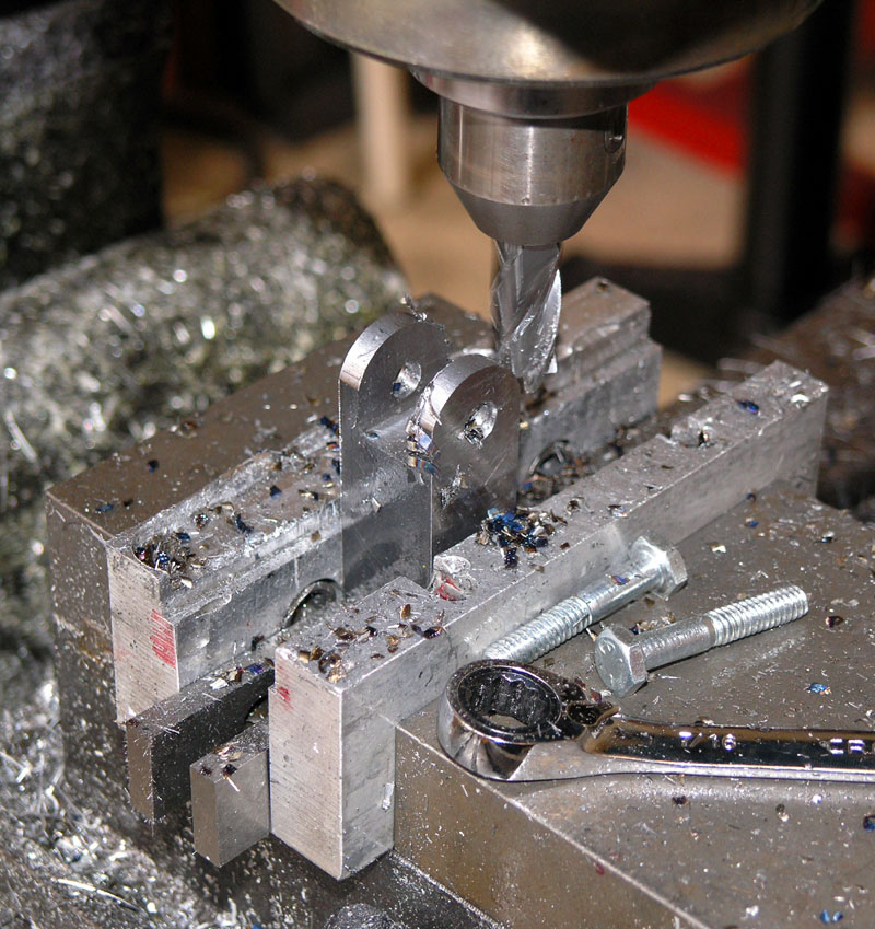
Fear not, those blue chips are from a different run that I didn't clean up with an inserted cutter! I was using my 5/8" Iscar Indexable Endmill to cut the male knuckle immediately before starting this run...
Installing the Mister on the Mill
I needed to set up an air supply for the mister, so I decided to set up a system to deliver air for 3 purposes:
1. Mister
2. Powered Drawbar
3. Auxilliary, probably a handheld blowgun
Some time ago I got a great deal on integrated air supply units that are really nicely made, so I just dragged one out, drilled and tapped a couple 1/4-20 holes on the back of the mill column, and voila:
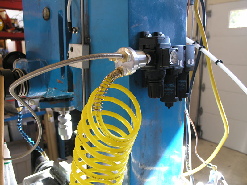
There is a quick release male connector on the backside out of view. Eventually I will plumb my air system to it permanently and remove the quick release...
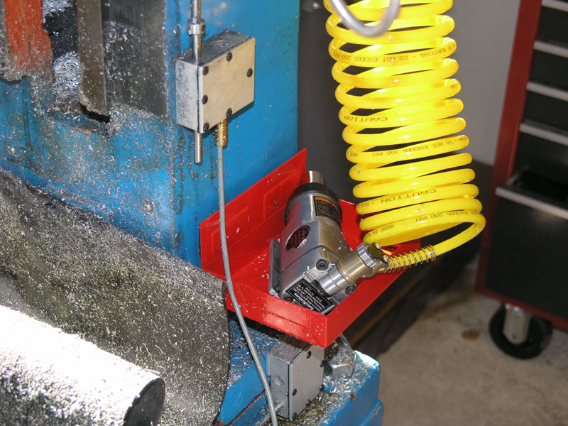
Here is my "powered drawbar". At the moment, its just a handheld butterfly wrench. Still speeds up tool changes a lot! The tray is magnetic, bought on sale somewhere. Very handy. I have a bunch festooned off various cabinets...
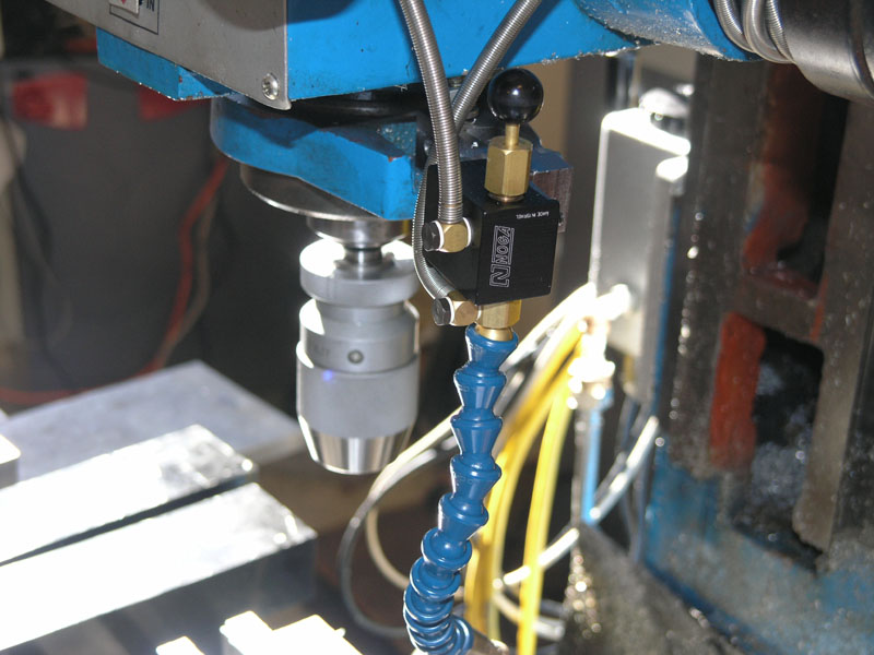
There is the little Noga mister. Got a steal on eBay. Pull the knob up to activate. Nice how the hoses are armored. One is a 1/4" NPT fitting to the regulator. The other is designed to drop into a bottle of KoolMist or whatever coolant you prefer.
Notes from Others
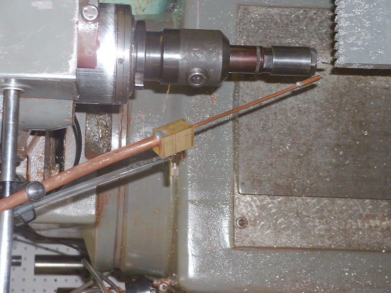
A similar mister in use...
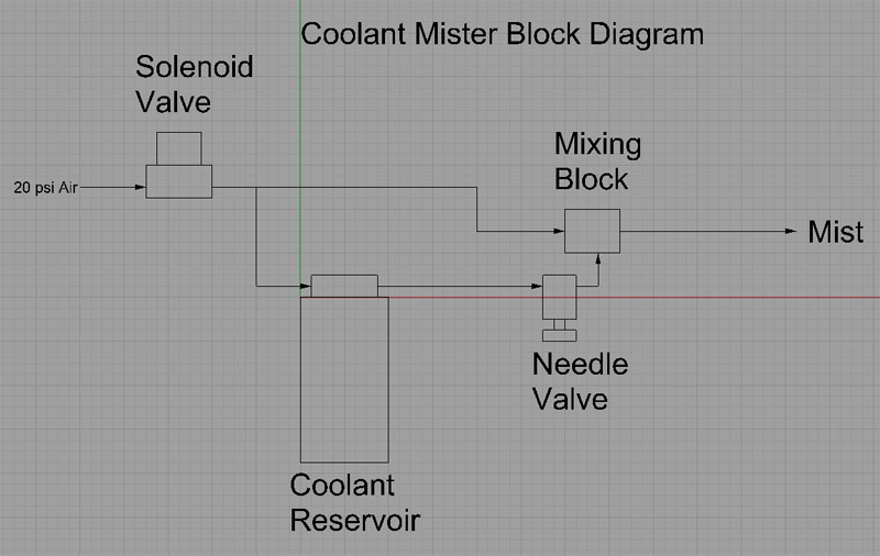
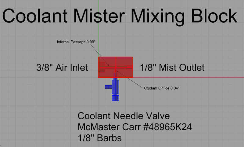
This is a "fogless" coolant mister. Feed up to 20 psi directly to the air inlet as well as pressurized to the coolant reservoir. The outlet is a straight shot of 1/8" OD copper pipe. One fellow used a 0.045" Mig tip as a nozzle on the end of that.
Other components needed:
Reservoir: McMaster Carr #4422K3
Electrical Solenoid Valve: McMaster Carr #4738K147
Miscellaneous Hoses and Fittings
Should be pretty easy to construct!
|
Do you want to be a better CNC'er in 37 Seconds? Get Better Tool Life, Surface Finish, and Material Removal Rates Fast. It's that easy. You can install and get results now.

|
||||||||||||||||||
| ||||||||||||||||||