|
|
|
|
|
|
|
Want to be a better CNC'er? Get our weekly newsletter plus a package of greatest hits, special tips, and more, all for free. I'm Ready to Be a Better CNC'er, Hook Me Up! |
Tuning Up My IH CNC Mill for Accuracy
Once I got my mill up and running, I wanted to check its accuracy and improve on it as much as possible. Note that this was not a factory CNC'd mill. I bought a used mill of indeterminate accuracy (I never used it before converting it) and then retrofitted the IH CNC kit to it. Not surprisingly, it was pretty far off the first time I attempted to use it. So, I embarked on a plan to fix that.
My method was to use a particular part, in this case a bearing block that was part of the Elmer's Comber Rotary steam engine. I would machine the block, inspect its dimensions with my Mitutoyo Digital Micrometers, make adjustments to the mill, and try again. This proved to be an iterative process, with a lot of "three steps forward and two back" sort of progress, but I must say I learned a lot along the way. I used the cumulative errors across every dimension as my measure on each trial of how I was doing. I also kept an eye on the average value of the errors, the worst error (what was it on, how bad was it, and what does it mean?), as well as looking at the errors relative to the axes. I listed X errors and Y errors in separate columns.
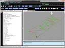
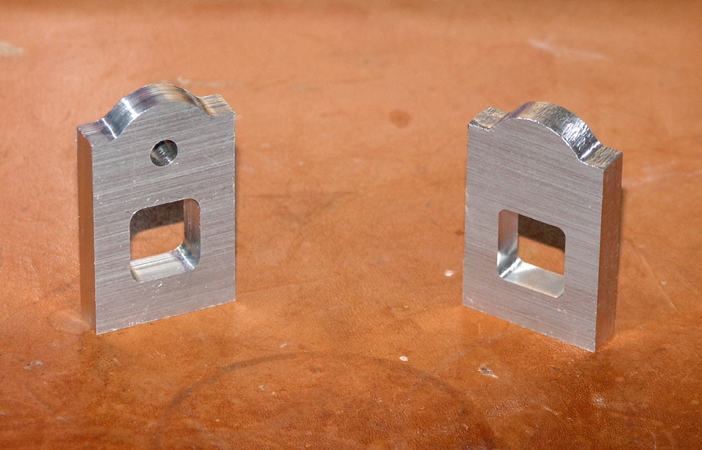
On this page, I'll go through each trial, show what errors I discovered, and talk about what I did to try to correct them and how that turned out. Here's what the parts look like, BTW:
A couple of very early trials...
Baseline Trial (Sum of Errors: 0.0414", Worst Error: 0.0121", Average Error: 0.0083")
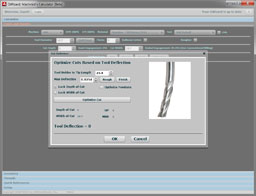
On this first run, I just could not believe the errors would be this bad. I had calibrated the steps per inch carefully and thought my mill would do a lot better. The worst error (0.0121") was in the distance from the bottom of the part to the bottom of the rectangular window. After scratching my head, I got to wondering whether the endmill was really cutting the diameter advertised. I was using a 3/16" endmill, which ought to cut a 0.1875" slot. So I devised a way of measuring the actual cut width. I took a piece of scrap, mic'd it, cut it in half, mic'd each half, and concluded the difference was the endmill's cut diameter. Mine turned out to be 0.1847" instead of 0.1875". That's a long ways off!
I asked around and the basic response was very high quality endmills are good to a few tenths, but that errors like I was experience were common for run of the mill (sorry!) endmills. DOH!
Trial #2: Entered the Actual Endmill Cutting Diameter into the CAM Program (Sum of Errors: 0.408", Worst Error: 0.107", Avg error: 0.0068")
Things were better, but still pretty bad. A couple of things suggested themselves. First, having discovered how far off my endmill was, I wanted to try another endmill from another maker. I ordered some 3 flute endmills from Maritool, which has a good rep on the PM Board. I've done business with them before and always been happy. I was careful to measure the true cutting diameter this time. The 0.1875" endmill was cutting a slot 0.1842" wide. Oh well, no more accurate. But it sure cut nice with the 3 flutes!
Second, I noted the Y-axis errors were much worse than the X. In addition, I got a fault or two on Y. So I retuned the Y servo.
Trial #3: Tune Y Axis + New Endmill (Sum of Errors: 0.0251", Worst Error: 0.009", Avg Error: 0.0042")
Much better!
So much better, I thought I'd try to tune things by "tweaking" the endmill's stated diameter in the CAM program. This is not unlike tweaking tool wear which is a common practice to keep accuracy.
Trial #4: Endmill Diameter Tweaked (Sum of Errors: 0.0174", Worst Error: 0.0092", Average Error: 0.0029")
Even better! Now we're cooking. At this point I could see no further rhyme or reason in which measurements were out. In addition, I'd been worried about encoder noise for quite a while since Mariss F. started complaining about problems with US Digital HEDS encoders. So I installed some bypass capacitors. This immediately necessitated some servo retuning, which I took as a good sign. In addition, I needed to recalibrate the steps per inch for both the X and Y axes, which also seemed a good sign. These were signals that the capacitors were doing something.
Trial #5: Capacitors on HEDs Encoders, Servo Retune, Recalibrate Steps/Inch (Sum of Errors: 0.0203", Worst Error: 0.0075", Average Error: 0.0034")
Trial 5 reflected a setback. While the worst error was improved, the sum of errors and the average of errors got worse.
I decided to recheck my cutter diameter. I also wanted to tighten the gibbs and check the backlash. The X-axis had 0.0006" of backlash, so I left it alone, but Y had 0.003", which is a ton for ballscrews! Hence I cranked up the preload and it actually got down to 0 measurable backlash on my Interapid 0.0001" indicator. Cool beans!
Time for another trial.
Trial #6: Changed cutter diameter to measured 0.1842", Tightened X,Y gibbs, Set Y preload for 0 backlash (Sum of errors: 0.0295", Worst error: 0.0110", Avg Error: 0.0049")
Can you feel my frustration? Every error measurement suddenly got worse. Fooling around with something else, I managed to break the endmill I had been using, so it was time to try a new one.
I measured it's cut diameter (0.1835", each one seems worse than the last!), and I decided to try less depth of cut. I had been running 0.050", but perhaps this was making the cutter deflect. I reran the CAM program to get g-codes with 0.020" depth of cut. Lastly, I hooked up my cold air gun and ran a continuous flow while cutting.
Trial #7: New endmill, Reduced Depth of Cut, Continuous cold air cooling (Sum of errors: 0.0387", Worst error: 0.0105", Avg Err: 0.0064")
Things got worse again!
I tweaked my cutter diameter again in the CAM program to a figure that as best I could determine would be optimal for both axes. It wasn't going to get rid of all the errors (they weren't symmetrical enough) but it would help. I was using 0.1855" instead of 0.1835".
Trial #8: Tweaked cutter diameter (Sum of errors: 0.0301", Worst error: 0.0081", Avg Err: 0.005")
That helped quite a bit. Still not as good as Trial #4, but directionally correct.
I recalibrated X,Y steps/inch yet again, this time using Mach3's calibrate function. I had broken the endmill on another project, so had a new endmill and went with the measured cutting diameter: 0.1805" this time.
Trial #9: Calibrated X,Y steps/inch, New 2 flute 3/16" endmill, cutter diameter set to 0.1805" (Sum of Errors: 0.0165", Worst Err: 0.0058", Avg Err: 0.0027")
We're back! Best run yet. Unfortunately, reducing the error from here is really a twitchy process with lots of setbacks. Getting used to it.
I decided it was time to square the mill column by leveling the machine and then shimming out the remaining error. I then trammed the head. I touched up servo tune again, and then recalibrated endmill diameter. The first run faulted on a Z move.
It turned out I just needed a few pumps on the one shot and things were moving again. I had forgotten to keep the lube flowing and the Z-axis works particularly hard due to the weight of the head. In any event, there were some pretty bad errors. You can't just restart after a fault too easily. Need to go back and relocate things. Not having home switches or other means, I just decided to start over and get a clean run. It did look like I need to bump up the endmill diameter to 0.1850 based on some other test I'd done.
Trial #10: Squared the Mill Column, Trammed the Head, Touched Up Servo Tune, Recalibrated Endmill Diameter (Faulted run)
I won't record the errors on this trial because the mill faulted, so it was way off. But I will talk a little bit about squaring the mill column. The goal is to make sure that when the head goes up and down, it does so square to the mill table.
Before attempting to square your mill, be sure to level the table. I measured my squareness before and after leveling and the difference was substantial. So substantial that you can probably get perfectly square just by tweaking the leveling feet of you mill, just like with a lathe.
Before attempting to square the column, be sure to level the table!
The easy way to check this is with a dial test indicator in the spindle, and a cylindrical square on the table. You need to measure 2 planes corresponding to X and Y, so I positioned the cylindrical square twice:
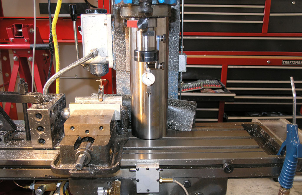
Cylindrical square is inline to measure whether the column "nods" forward or backwards from vertical. The indicator should stay put as the head jogs up and down...
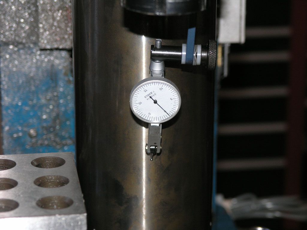
I started at the top and went down 8". The need barely moved a tenth!
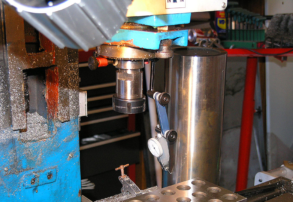
Now we rotate 90 degrees and we're going to check whether the column leans left or right by moving the head up and down and checking against the square...
I was out about 1 thou left to right and nearly 3 thou of "nod" forward. This was easily fixed with a little shim stock. Having squared the head, I went on to tram it as well.
Trial #11 (Trial #10 faulted): Tweaked endmill diameter to 0.1850" (Sum of Errors: 0.0165", Worst Error: 0.0047", Avg Error: 0.0028")
Things are nominally better. At least the worst error got better even though the sum of errors is the same and the average error is a tenth worse (that tenth is in the realm of experimental error, this machine won't be accurate to tenths, so ignore it!).
At this point, I had been frequently checking the Smoothstepper support boards to see when backlash comp would be available. I couldn't help but wonder whether that was my problem. While i had no Y backlash, X had 0.0006". Maybe that was working against me. I came across some notices that there were some pretty significant positioning problems fixed in the latest couple of smoothstepper releases. I checked, and sure enough, I did not have those releases, so I downloaded and reinstalled them.
Trial #12: Latest Smoothstepper Drivers (Sum of Errors: 0.0381", Worst Error: 0.0141", Avg Error: 0.0064")
Wow, backtracking again. Sure kinda wished I hadn't installed that update, but not sure it's a great idea to roll it back either.
At this point I decided I needed more information on what the mill was doing. I have a Fagor DRO, accurate to 0.0002", that I bought for a lathe. It's only 2 axes, but I decided to mount this DRO to the mill's X and Y axes and try to analyze more closely what was going wrong. Hopefully this would let me be a lot more systematic in my diagnosis because I'd have a lot more information.
Trial #13: Fixed X-Axis Backlash, Recalibrated X Using DRO, Remeasured Cutter Dia to Actual (Part Faulted, but still was within an average of 1.4 thou!)
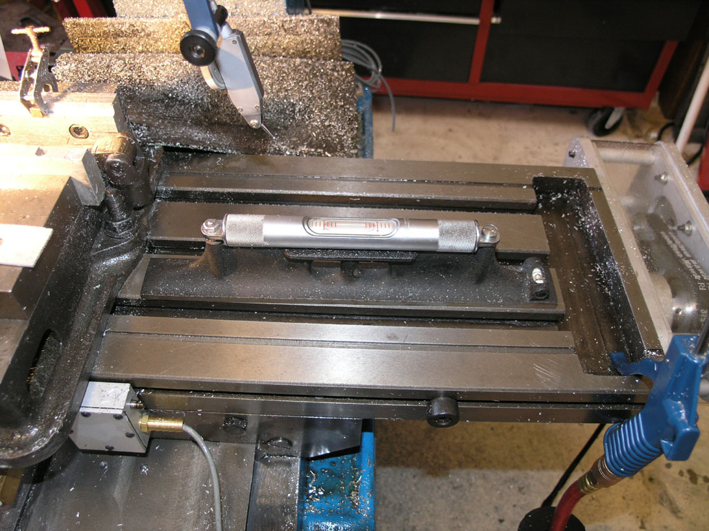
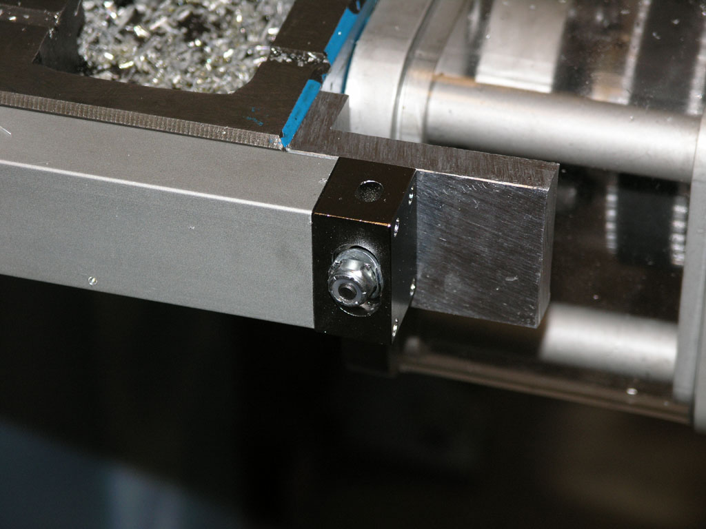
Here is the X-axis DRO:
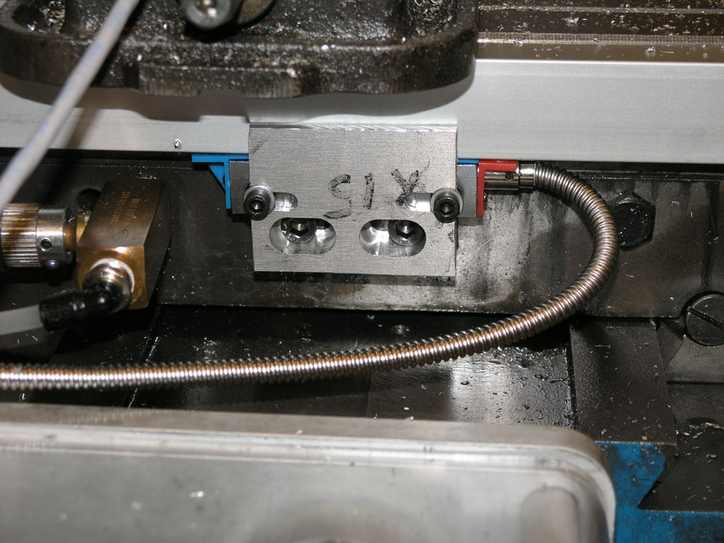
The reader head mounts where the home/limit switch goes. The DRO is only temporary and I didn't want to make any new holes in my mill! Note how the bracket protects the head a bit...
Each end of the scale is held by a little L-shaped bracket. You need to be able to tram the DRO in so it is level and square with the table...
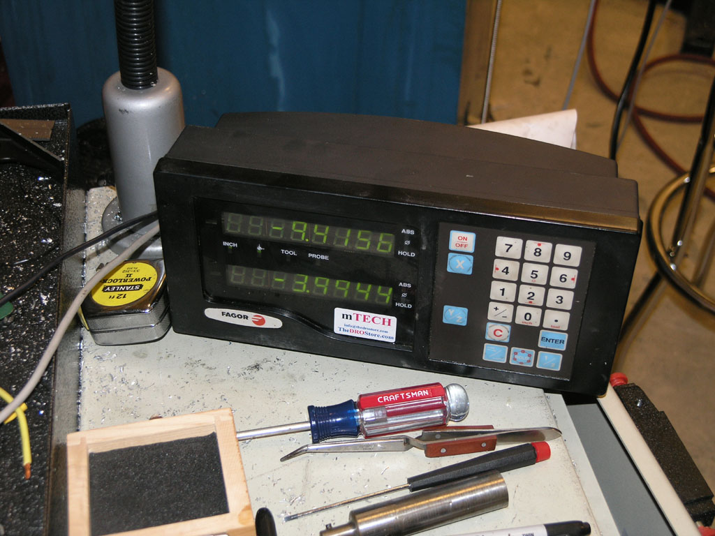
And here is the control panel for the DRO...
The bracket was very easy to make using the CNC Wizards in Mach3, and especially the Newfangled Wizard. Here are some pix of the construction of the reader head bracket:
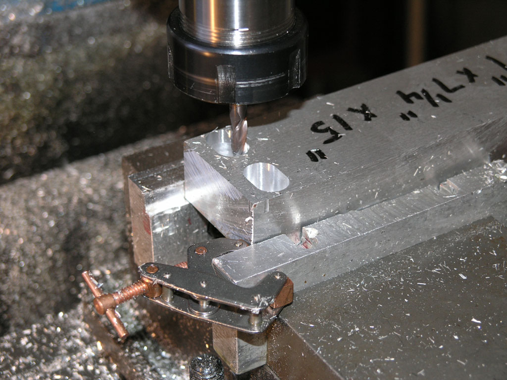
Slotting for the mounting bolts...
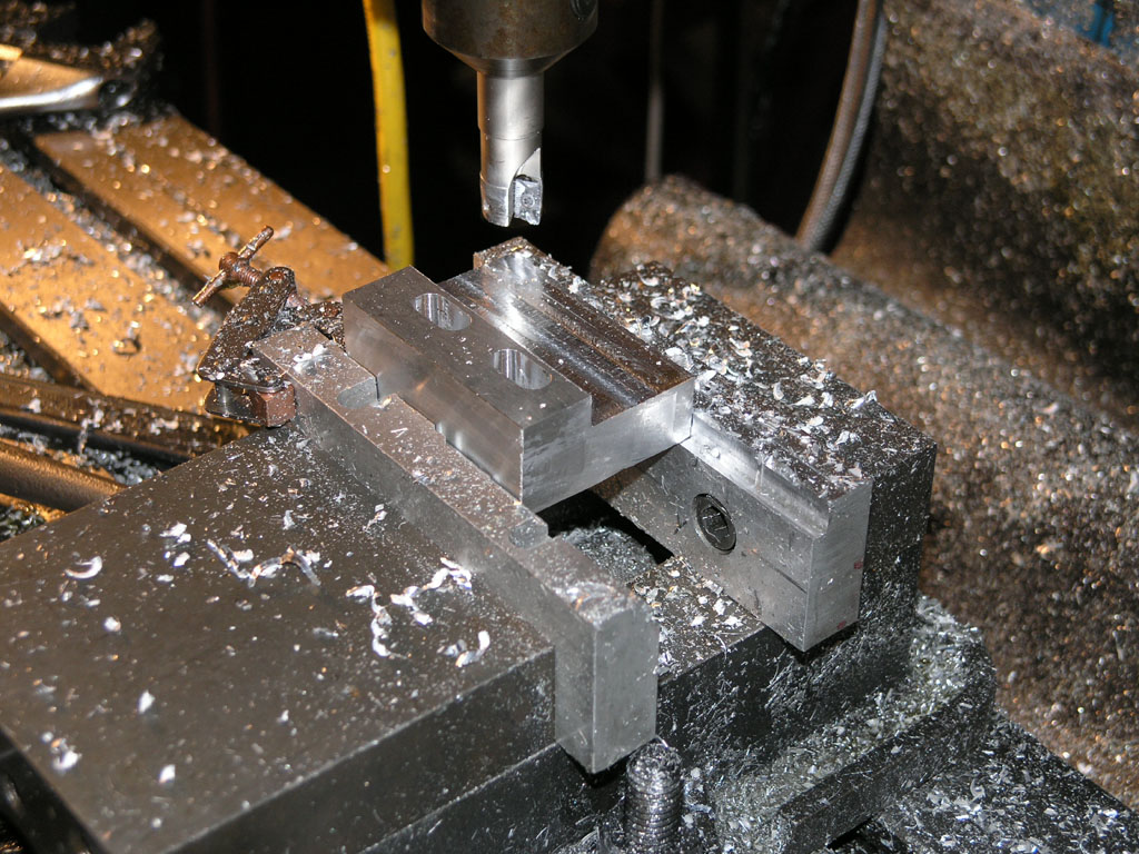
Love my 5/8" Helimill. Those APKT inserts cut through aluminum like butter!
As soon as I got the DRO installed I immediately uncovered my major malfunction ("Private, what is your major malfunction?" asked the Drill Sergeant in Full Metal Jacket). It turns out the preload for my X-axis ballscrew had come loose and I had nearly ten thousandths of backlash! Darn, the first time I measured it was just a few tenths. This explains a lot!
I tightened the preload again and rechecked backlash with the DRO. Still a bit high, so I loosened by X gibb slightly. Aha! That helped too. I had things locked up too tight.
I ran my part again, but managed to fault. This is usually because I've let the ways dry out. Got to remember to pump that one shot because I'm running the gibbs really tight as I keep saying. I need to go through and gradually loosen them until I see backlash pick up and then use that as my setting.
Even after faulting and using my edgefinder to relocate the part, all features were within 1.4 thou on average of the expected. My guess is I'll be able to get well under a thou in another trial or two!
Meanwhile, I thought I'd map my X ballscrew just to check its accuracy with the DRO. Here is what I found with a series of half inch jogs:
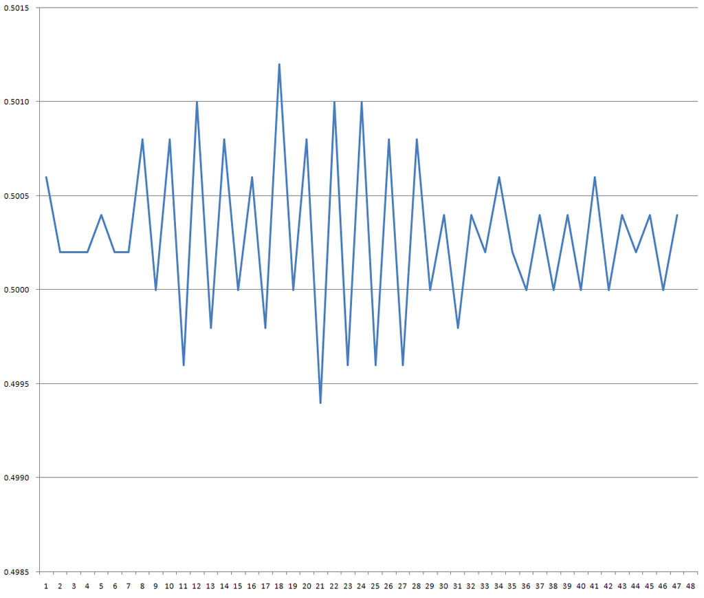
The left axis shows the actual move of each commanded 0.5000" move as measured by the DRO. If the ballscrew were perfectly accurate, the graph would be a straight line centered on 0.5000".
You can see the righthand 40% of the ballscrew is qutie a bit more accurate than the left, although the first maybe 10% on the left is quite good too. Nevertheless, the whole screw moves to well under a thousandth of accuracy. You can also see that the errors are not cumulative, but are more periodic. The total error in 24 inches of motion was 5.6 thousandths and the screws are advertised as having less than 3 thou per 12", so this screw is within spec.
|
Do you want to be a better CNC'er? Get Better Tool Life, Surface Finish, and Material Removal Rates.
|
||||||||||||||||||
| ||||||||||||||||||