FAQ
General:
- Should I use Serial or USB?
- Do settings get erased from the 3DM-CV7 if I unplug it?
- How do I upgrade firmware?
GNSS:
- Can I use a different GNSS antenna than the default U-Blox antenna?
- Does the 3DM-CV7 have anti-spoofing or anti-jamming capability?
- How do I measure the antenna offsets?
- What are the mounting requirements for using Dual-Antenna heading?
- How do I improve dual antenna heading performance?
RTK:
- Why did the 3DM-CV7 lose an RTK Fix?
- Is the 3DM-CV7's RTK solution guaranteed?
- Is the SensorCloud RTK corrections stream guaranteed?
Navigation Filter:
- Why is the filter stuck in Vertical Gyro Mode?
- How do I improve Navigation Filter performance?
- How do I know when I can trust the Navigation Filter solution?
- How do I interpret the Filter Status (0x82,0x10) message?
- Can the 3DM-CV7 navigate during a GPS outage?
Support
Software:
- Does MicroStrain by HBK have data visualization tools?
- Does MicroStrain by HBK have ROS drivers?
- Does MicroStrain by HBK have PX4 drivers?
- Does MicroStrain by HBK have ArduPilot drivers?
General
Do settings get erased from the 3DM-CV7 if I unplug it?
- It depends. The 3DM-CV7 will use the existing "startup settings” stored in the device unless the settings are saved prior to power down. To save the settings, do one of the following:
- In SensorConnect, click “Save as Startup Settings” in the “Save/Load” tile.
- In SensorConnect, click the checkbox “Save as Startup Settings” in the “Streaming” tile.
- In ROS, set the "save_settings" param to true and successfully launch the node
- In MSCL, use the node.saveSettingsAsStartup() function.
- Use the Device Settings (0x0C,0x30) command with the SAVE function selector.
- In SensorConnect, you can also export a .json settings file to your local computer that will save your full device configuration, which can be loaded again in the future.
How do I upgrade firmware?
-
Please see the Firmware Upgrades page for methods and instructions on upgrading device firmware.
RTK
Why did the 3DM-CV7-GNSS/INS lose an RTK Fix?
- The most common cases of losing an RTK Fix are:
- Loss of comms to RTK corrections: cell signal dropped, radio line of sight is obstructed, satcom obstructed, WiFi out of range, etc. Check comms
- Poor sky view / "high multipath": trees, buildings, parts of vehicle obstructing a 45° inverted cone above each antenna. Ref Antenna(s) page Multipath
- EMI (Electro Magnetic Interference): From antennas or antenna cable coiled near compute, lights, motors, relays. Ref Antenna(s) page EMI
- No groundplanes: groundplanes under patch antennas is critical to their satisfactory operation. The default 3DM-CV7-GNSS/INS antennas do not have groundplanes built in and unless mounted on a flat metal surface, like a roof of vehicle, can struggle. Ref Antenna(s) page Multipath
- Incorrect credentials: manually selected base station mountpoint is incorrect and too far away (rover RTK error increases at 1cm + 1mm/km from base station). Check mountpoint is correct
- Base station offline: review provider's coverage map
Is the SensorCloud RTK corrections stream guaranteed?
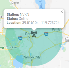
- We simplify the network and interface process to provide you an all-in-one navigation solution. This solution includes our 3DM-CV7, 3DM-RTK and SensorCloudRTK service. We work with RTK and cellular providers to deliver the SensorCloudRTK service. As we do not own those provider’s networks we cannot control their operational behavior. SensorCloudRTK Coverage Map provides a real-time database showing base stations' ID, location, operational status and range as shown in Figure: SensorCloudRTK Example Base Station Info
Figure: SensorCloudRTK Example Base Station Info
Do I need to use the 3DM-RTK and SensorCloudRTK to receive RTK corrections?
- No, we have outlined several ways for the 3DM-CV7 to receive RTK corrections in the "4 Ways to RTK" app note and many more have been added since.
- For ROS users, head to the ROS NTRIP client node, compatible with our ROS1 and ROS2 drivers.
Navigation Filter
Why is the filter stuck in Vertical Gyro Mode?
- The filter is likely stuck in Vertical Gyro Mode because it does not have sufficient initial conditions. See Filter States for more info on Vertical Gyro Mode.
- In Vertical Gyro Mode, the Navigation Filter is only reporting valid gyro stabilized pitch, roll, and the change in heading relative to the initial orientation. To transition to Full Navigation mode, the Navigation Filter requires the initial conditions for all states shown in the table below. These can be provided to the Navigation Filter through the Initialization Configuration (0x0D,0x52) command. The time to transition from power on to Full Navigation mode under ideal conditions is typically less than
| Filter Mode | Filter State Value | Initial Conditions Required | Available Outputs |
|---|---|---|---|
| Initialization | 1 | None | None |
| Vertical Gyro | 2 | Roll, Pitch (from IMU) | Roll, pitch, relative heading |
| AHRS | 3 | Absolute heading | Roll, pitch, absolute heading |
| Full Navigation | 4 | Absolute heading, initial position, initial velocity | Roll, pitch, absolute heading, position, velocity |
- Ensure 3DM-CV7 is configured correctly - see Filter Aiding Measurements
- If the 3DM-CV7 hasn't converged in
How do I improve Navigation Filter performance?
The time to transition to the Full Navigation filter mode is less than
- Ensure that your firmware is updated to the latest version.
- Ensure antennas are correctly installed, and if using dual antenna, that their offsets are not accidentally swapped (a common problem).
- Ensure the proper Filter Aiding Measurements are enabled.
How do I know when I can trust the Navigation Filter solution?
It is highly recommended to read the Navigation Filter section of the manual. You will need to configure the device to stream the data fields that contain the status information required for your application. Upon receipt of the status fields, you will need to set thresholds for the data based on your application's requirements, for example:
- The Status (0x82,0x10) message provides two important pieces of information for the user: the current Filter State (AKA mode) and Status Flags that provide real-time warnings about the filter's condition and its estimates.
- The Status (0x82,0x10) message will report values of 4, 1, 1, when the Navigation Filter is in normal operation. These numbers correspond to Full Navigation Filter State, Default Dynamics Mode, and Converged filter Status Flags.
- See "Interpreting the Status data channel" below for more info.
- Filter Position Uncertainty Messages
- The user must decide what position uncertainty values are required for their application. Typical 1σ values are:
- Single point: 1.25-2.5m
- RTK-Float: 0.1- 0.8m
- RTK-Fixed: 0.01 - 0.06m (error model assumes maximum base station baseline of 50 km)
- Position uncertainty is available in different frames in the following messages:
- The user must decide what position uncertainty values are required for their application. Typical 1σ values are:
- Euler Angles Uncertainty (0x82,0x0A)
- Set application specific Yaw (heading) uncertainty threshold
- Verify uncertainty is below threshold
How do I interpret the Status (0x82,0x10) message?
The data fields reported by the Status (0x82,0x10) message are the Filter State, Dynamics Mode, and Status Flags. The Status Flags is a bitfield that must be properly interpreted:
- SensorConnect's Status QuickView performs the conversion for the user into easy to understand text.
- The ROS drivers RQT Status QuickView GUI performs the conversion for the user into easy to understand text.
- If converting manually, a simple online decimal to binary converter or calculator application in "programmer mode" will work.
- For embedded applications, a simple bitshift calculation is required.
- We recommend the user checks for the Filter state = 0x04 and Status flags = 0x01 or 0x02 (i.e. no warnings are raised and the filter condition is either stable or converging) at minimum to verify satisfactory filter performance.
Ex: What does 4, 1, 1025 mean from Status (0x82,0x10)?
- One can use any decimal to binary converter, we see the 0th and 10th bit have values of 1.
- The 0th and 1st bits correspond to the Filter Condition,as described on the Filter Status Flags page. The 0th bit indicates a Filter condition of Stable. This is desired so is not the cause of concern.
- The 10th Status Flag bit corresponds to a time sync warning as seen in the table below with the 10th bit's row highlighted in yellow. This means no PPS source is detected and the recommended action is to check the PPS source is set correctly i.e. ensure an antenna is connected for the PPS source selected.
| Bit # | Bit Value | Description | Potential Cause | Recommended Action |
|---|---|---|---|---|
| 0-1 | 1 | Filter condition (Stable/Converging/Unstable) | Insufficient initial conditions supplied. | Verify required conditions are properly enabled. Review Filter States. |
| 2 | 0 | Roll/Pitch Warning | Sensor is not aligned with vehicle frame. | Review Vehicle Frame page. |
| 3 | 0 | Heading Warning | Heading source is not valid. For Dual Antenna: Multipath, EMI, incorrect antenna offsets. For Magnetometer:time varying magnetic interference. | For Magnetometer:perform Magnetometer Calibration, check for time varying magnetic interference via Scaled Mag (0x80,0x06), if present use |
| 4 | 0 | Position Warning | Multipath, EMI, incorrect antenna offsets, antennas obstructed, antenna cable shorted. Review How to improve filter performance above. | Review: Antenna offsets, FAQ: Antenna sections, FAQ:How to improve filter performance. |
| 5 | 0 | Velocity Warning | ||
| 6 | 0 | IMU Bias Warning | Gyro bias is high. | Perform Capture Gyro Bias (0x0C,0x39) |
| 7 | 0 | GNSS Clock Warning | Multipath, excessive vibration. | Not critical concern - continue navigation. |
| 8 | 0 | Antenna Lever Arm Warning | Antenna Lever Arm offsets are likely incorrect. | To improve performance, review Antenna(s) page. |
| 9 | 0 | Mounting Transform Warning | Transform is likely incorrect. | Review Vehicle Frame page. |
| 10 | 1 | Time Sync Warning | No PPS source detected. | Check PPS source is set correctly i.e. GNSS receiver 1 = PPS 1 |
| 12-15 | 0 | Solution Error | Filter computation warning flags. If any bits 12-15 are set, all filter outputs will be invalid. | Reset Navigation Filter (0x0D,0x01) |
- Note: the filter condition occupies 2 bits (bits 0 and 1) and can be interpreted as shown below (see Filter Status Flags page for more info).
| Filter Condition Values | Description |
|---|---|
| 1 | Stable |
| 2 | Converging |
| 3 | Unstable/Recovering |
Can the 3DM-CV7 navigate during a GNSS outage?
-
- In cases where outages longer than 60 seconds are expected, and depending on the position accuracy requirements of the application, we typically recommend using additional
- For UAS and USV higher uncertainties may be allowable in which case the user may continue to navigate without these aiding measurements, while monitoring the navigation solution as described above. The 3DM-CV7 can continue to navigate but its position error will increase exponentially, as is the case on the majority of INS systems.
Data
Is the bias removed from Compensated Angular Rate (0x82,0x0E) and Compensated Acceleration (0x82,0x1C) data channels?
Yes, but the Compensated Angular Rate or Compensated Acceleration messages are not anti-aliased at this time. This means, if you choose a sample rate lower than 500 Hz, aliasing can occur, which looks like noise but is actually due to down-sampling. This shortcoming is being addressed in the next firmware release.
Support
How do I obtain Engineering Support for my device ?
MicroStrain Support Engineers can be contacted through many methods. Please review the Support page for more information.
Software
Do you have data visualization tools?
Does MicroStrain by HBK have ROS drivers?
Yes, and we have examples, and a dedicated ROS Engineer to support them and support you! See the Software page for more information.
Does MicroStrain by HBKhave PX4 drivers?
Yes! Please see the Software page for more information.
Does MicroStrain by HBKhave ArduPilot drivers?
Yes! Please see the Software page for more information.