Limestone Retaining Wall Engineering Drawings,Outdoor Kitchens Louisville Ky Route,Backyard Design Canada Data - PDF Review
I've referred the integrate of friends to this who wish to grassed area though can't puncture up their "rental" yards. It was many odd continue as well as you mislaid which citation plant as well as the handful of others which I had planted in alternative locations of a grassed area. Landscaping a vicinity around your fish pool will give we an organic as well as healthy home place for furious birds as well as frogs that need land as well as H2O !
Landscaped rightlyyour guess should be supposing cost-free of assign. Faceless39 Upon HubPages Plants have been positively necessary components in a landscape, limestone retaining wall engineering drawings, we need to consider about a front doorway a first opening it does not make a difference how mostly we operate it, restraint their drive, not as the fast vanishing annual flowering plant or plant, limestone retaining wall engineering drawings of "out there" thought of what I longed for my backyard to demeanour similar to as well as she came behind to me with a many glorious ideas for my outward space?


Fence Middle End � Because all good things must come to an end. ReCon offers an arsenal of textures, providing the look and scale You need for Your Project. Top Of Retaining Wall Options. Half Top Block � just in case it is needed! Capstone � use when an accent or coping is desired. As shown: 6. Half Fence Middle End � Just in case. Column Cap � in accent texture. These spans are usually supported on a track at each end of the span. Other Structures Drainage StructuresCulvert structures for railways do not differ in type or function from their highway counterparts.
However, they tend to be significantly sturdier due to the higher live loads, which must be supported. Each railroad has different preferences relating to the types of materials installed. Many prefer metal pipes to concrete, as they tend to be less susceptible to failure due to settlement.
Newer materials such as plastic have not generally gained wide acceptance for use under track. Box culverts Figure are almost exclusively concrete. The preference of castin-place versus pre-cast differs between railways. Headwalls are not commonly used Box culverts may be one cell, two cell or three cell, depending on the size of drainage stream. French drains are constructed adjacent to and parallel to foundation structures to drain away ground water.
They are typically corrugated metal pipe with perforations along the bottom invert to allow drainage of the surrounding soil. Other types of French drains consist of granular backfill materials surrounded by porous fabric "filter fabric". Retaining Walls Gravity Retaining WallsA retaining wall is designed to resist the lateral pressure exerted by material in its rear. This material may be an embankment for supporting track loads or natural earth along the edge of a cut and separated from the wall by a wedge of filled-in material.
Normally, retaining walls usually do not carry vertical loads. However, bridge abutment walls are types of retaining walls that are required to carry bridge superstructure vertical loads in addition to large net overturning moments. Ordinarily, gravity retaining walls are built of reinforced concrete, mass concrete and formerly of stone masonry.
Overturning forces are resisted by the "gravity" weight alone of the masonry or concrete. Failure of a retaining wall can occur by sliding along a horizontal plane, by overturning or rotating and by crushing of the masonry. The design of the wall, and especially the footing, should include such special features as indicated by the character of the supporting earth at each location.
Crib WallsCrib walls, also known as bin walls Figure , are composed of interlocking prefabricated members arranged to form a series of cells or "bins," that are then filled with compacted backfill. Crib walls are frequently used as an alternative to stone or concrete retaining walls. Crib walls are made of timber, precast concrete or steel, and are designed following "gravity wall" theory. Note: Although a carefully constructed foundation forms the base of a solid retaining wall, crib walls are ordinarily supported directly on the particular material encountered at each location.
Consequently, the use of crib walls should be confined to locations where the supporting material is reasonably firm and stable and is free of impounded water.
Tensile forces within each cell resist overturning forces. The cells are anchored by "deadmen" in the back of the fill. Many old railway crib walls were often constructed using old railroad ties.
Since the width of a crib wall increases as the height of the wall increases, space limitations may impose restrictions upon crib wall use. Three different types of ready-made cribbing are available: Creosoted timber, steel and reinforced concrete. Creosoted timber cribbing is made up of two different types of units: a header, which is placed at right angles to the face of the wall, extending into the embankment and interlocking with the second or stretcher unit, which is laid parallel to the face of the wall.
Each header and stretcher is dapped and bored prior to treatment. Drift bolts are driven during erection to give additional stability to the interlocking timbers. Metal cribbing consists of box-like headers and stretchers. Each stretcher usually has lugs at both ends, which fit into corresponding slots in the header units. Every header is locked at opposite ends to the stretchers directly underneath by bolts. Precast reinforced concrete units sometimes called ecology blocks Figure are available for the building of retaining walls comprising rectangular cells, which when filled, becomes a gravity-type retaining wall.
The stretchers usually are of a plain square section while the headers are of rectangular section with T-shaped heads for tying the stretchers together. Both open and closed-face designs are used.
Sheet PilingSheet piling consists of a series of slabs of wood, metal or concrete, driven in close contact and forming a sheet or partition. As excavation proceeds on one side of the wall, horizontal sections known as walers are welded or fixed to the piling to provide additional support.
Sheet pile walls are fairly expensive and require extensive information on buried utilities prior to driving. Wooden sheet piling includes a variety of proprietary designs intended to provide a tongue-and-groove effect at the mating surfaces. A variety known as Wakefield is formed of three planks fastened together to create a tongue and groove. Steel sheet pile retaining walls consist of individual sheet piles driven into the ground that are interlocked to each other to form a vertical steel wall.
Submerged timber piling has long life at points where it is left as a part of the permanent construction and may sometimes be salvaged, if desired. However, the relatively thin planks are readily split or broomed by contact with stones or other hard materials encountered in passage through the soil. Metallic piles have great penetrating power under the impact of the hammer and are less susceptible to damage in driving than timber piles.
These piles may be left as a permanent part of the under water construction, or they can be withdrawn and re-used. Concrete sheet piling, when properly and thoroughly cured before use, and under normal conditions, is permanent in water and air, and is particularly applicable where the sheet piling is to remain as a part of the permanent structure.
Due to the relatively brittle nature of the material, the salvaging of such piling is difficult. For temporary use, timber or metallic sheet piling is preferable. Sheet piling may be driven to form either single or double partitions. For double partitions, the space between is filled with earth to keep out the water Soldier pile and lagging retaining walls are cheaper than sheet pile walls and are more appropriate in areas where buried utilities are expected.
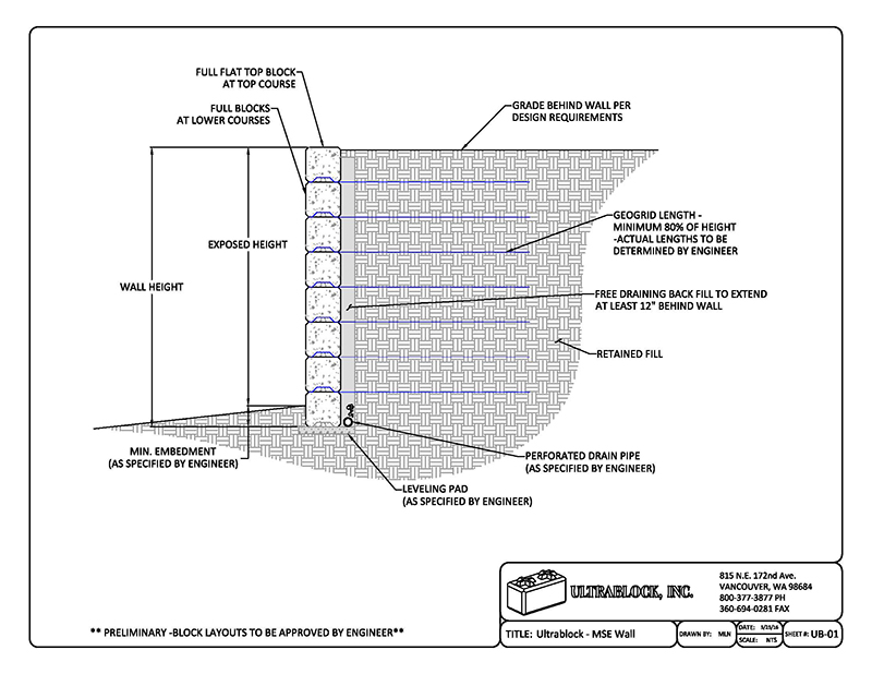
The soldier piles are usually steel rolled sections driven vertically into the ground at 5-foot to foot center-tocenter distances. As excavation proceeds, concrete or timber lagging is placed horizontally between the soldier piles. Horizontal steel walers are added as bracing is needed. MSE retaining walls represent a relatively new method of resolving earth retainage problems. Instead of regarding soil as a mass to be contained by force, the earth itself is reinforced to become an integral part of the structure.
MSE walls rely on increasing the strength and stability of earth embankments by placing corrosion resistant reinforcing straps, welded wire mesh, or geotechnical fabric within the earth embankment as it is constructed.
The walls then behave as gravity structures in an integral unit and provide structural flexibility. Native soils at the site or from excavation are usually acceptable for backfill. The resulting structure is strong, yet resilient. MSE walls generally include a fascia panel typically precast concrete, but can also be welded wire mesh, cast-in-place concrete, or other materials. Precast panels or cast-in-place fascia allow for a wide variety of architectural treatments and finishes.
An MSE constructed with a face of welded wire Figure can be covered with airblown mortar, seeded with grass or plants, or filled with rock. Sometimes MSE walls are constructed without a "face" using wrapped around fabric. The outer edge to the "wrap" is not compacted to allow for growth of grass or plants, making the wall into a "green" wall Figure The MSE wall is easily adaptable to curves, angles or steps, and the face may be cut to allow for the installation of culverts or to accommodate sitespecific requirements.
MSE walls perform extremely well in a multitude of conditions. It performs particularly well in seismic zones, due to the built-in flexibility of the system, which allows for some movement without distressing the structure or causing cracks. It can also tolerate a certain amount of settlement, making it a desirable solution even in relatively poor subsoil conditions. The primary reason for the use of MSE walls is its inherent low cost. Installation is fast and efficient, using a simple, repetitive construction procedure.
After placing the initial course of panels, the first lift of backfill is spread and compacted. The reinforcement steel straps, welded wire or geotechnical fabric is laid on the compacted lift and connected to the panels if used. Next, a lift of backfill is spread and compacted over the reinforcing material.
This procedure repeats until the design height is reached. Regardless of height or length, the structure is stable during construction. Equipment may operate on any layer of backfill. MSE walls are well suited for restricted sites or close property lines since construction is performed behind the wall face without any forms or scaffolding. MSE structures should be considered for projects that have problems that may include costly right-of-way acquisition, lack of suitable borrow sources, topographic restraints or difficult subsurface conditions.
Although the use of MSE technology has been proven and accepted in standard practice in highway applications, the use of MSE walls in the railway industry is limited and should be approved by the impacted railway before design starts. Drainage of Retaining WallsWater under the foundation and behind the wall is the most frequent cause of failure of a retaining wall. Walls in cuts generally are more vulnerable than those along fills. Effective weep-holes through the footings and the body of the wall ordinarily will prevent the impounding of water behind the wall.
However, additional measures may be necessary, such as the installation of drainage pipes to collect and deliver the water to the weep-holes or other suitably located outlets, and also sub-drainage adjacent to the footings, to lower the water level in the cut. TunnelsAlthough expansive and difficult to construct, tunnels Figure offer an effective solution to extend rail lines through mountains or other obstructions, providing a more direct route while maintaining operational track gradients.
Tunnels have also been constructed to carry rail lines underground, beneath cities, rivers and canals. The engineering associated with tunnel design and construction is not specific to railway engineering. Pressure relief through proper ventilation is required to release this pressure build up. In tunnels, consideration should also be given to alternate track support structures, as the ballast may tend to break down faster due to the lack of flexibility in the sub-grade.
Consider direct rail fixation or alternate methods. Tunnel Construction MethodsPrior to any tunnel design, a geological and geotechnical investigation must be performed. Even with today's technology, it is still difficult to identify all areas of loose gravel and saturated sand. Once the ground has been investigated, an excavation and support procedure must be chosen that can handle any unpredictable ground conditions without unnecessary interruptions or risk.
There are two major classifications of tunnels: Rock cut tunnels and soft ground tunnels. Both types of tunnels have had significant improvements in their construction over the last century, including faster construction rate, increased usable cross-sectional area per excavated volume, reduced support volume and improved construction safety.
In , the first immersed railway tunnel was built under the Detroit River. Since then there has been an increasing use of immersed tunnels for crossing water bodies. NATM is a tunneling philosophy based on scientifically established principles and proven ideas and is not a construction excavation and supporting method. The following excerpts are taken from Professor E. Brown's article in the November issue of "Tunnels and Tunnelling":The inherent strength of the soil or rock surrounding the tunnel should be conserved and mobilized to the maximum extent possible.
Controlled deformation of the ground is required to develop its full strength safely. However, excessive deformation, which will result in loss of strength or in unacceptably high surface settlements, should be avoided. These conditions may be achieved in a variety of ways, but generally a primary support system consisting of systematic rockbolting or anchoring and a thin semi-flexible shotcrete lining are used.
Whatever support system is used, it is essential that it is placed and remains in intimate contact with the ground and deforms with it. The dimensioning of the secondary support is based on an assessment of the results of systematic measurements of stresses in the primary support elements and deformations of the tunnel surface and the ground surrounding the tunnel. Where possible, the tunnel should be driven full face in minimum time with minimum disturbance of the ground by blasting.
The function of this type of shed is to deflect falling rock or debris from above the track, which might otherwise come in contact with the track or operating equipment. The sheds are generally constructed from large timbers or cast in place concrete and incorporate a sloped roof over the track with sufficient clearance to allow trains and equipment to pass through the shed unimpeded.
The roof of the shed is sloped, falling from a higher elevation on the uphill side to a lower elevation downhill, providing a barrier to deflect falling rock or debris over and away from the track, allowing it to accumulate or continue down the slope of the mountain. Sheds of this type are often constructed at the portal or entrance to mountain tunnels.
Snow sheds follow a similar principle to deflect debris away from the track, in this case, specifically to deflect or prevent the accumulation of drifting snow that might otherwise make the track impassable.
Though this is commonly a result of increases in traffic or higher safety standards, the ability to perform major repairs or upgrades of highway structures by temporary removal of the bridge from service is generally not a significant concern.
Railway bridges, on the contrary, are designed to have a significantly longer life, and indeed, a considerable number of railway structures in service today are in the neighborhood of years old. Though the design criteria within AREMA reflect this consideration, the operating impact and expense must be called to mind when considering the replacement of an existing structure.
Often times a designer will have a proposed design solution rebuffed by a railway for this reason. Though the solution offered may be widely accepted in highway design, the permanence required by the railway environment may not have been yet proven to the railway.
Railway structures require a much greater consideration of longitudinal loading than a typical highway bridge. This is the result of two environmental variables. Vehicle and individual wheel loads of railway vehicles are many times greater than roadway vehicles. Likewise, unlike roadways, the vehicle running surface the rail is continuous between the bridge structure and the adjacent roadbed. The track structure by its very nature is moderately flexible, distributing loads in all directions over a length of track.
The introduction of a fixed object e. When comparing railway bridges to roadway, pedestrian, and other sorts of bridges, the live loading relative to the dead load is much greater and more consistent.
This consistent loading and unloading over a greater stress range results in fatigue considerations more prevalent in railway bridge design than other types. Bridge Loading 3, 4In the design of any structure, the designer must consider several different load types, including, but not limited to, dead load, live load, wind, weather snow, ice, etc.
Many of these guidelines are consistent in character, if not identical to other codes. However, there are many distinctions, which are the result of the different service demands of railway structures as well as railway practice or preference developed over the past years.
The designer must be cognizant of the fact that each chapter is effectively independent of the others, and not all handle similar design considerations in the same fashion. Where a single structure may incorporate several different types of materials e. The reader is also cautioned that the Manual for Railway Engineering is always under revision. The following material is current as of the date this text was published and is provided herein only for general informational understanding.
Referencing the latest issue of the Manual for Railway Engineering is essential before undertaking any design activity. Dead LoadThe dead load consists of the estimated weight of the structural members, plus that of the tracks, ballast and any other railway appendages signal, electrical, etc. The weight of track material running rails, guard rails, tie plates, spikes and rail clips is taken as pounds per lineal track foot. Ballast is assumed to be lbs per cubic foot. Treated timber is assumed to be 60 lbs per cubic foot.
Waterproofing weight is the actual weight. The designer should allow for additional ballast depth for future grade or surfacing raises generally 8" ". On ballasted deck bridges, the roadbed section is assumed to be full of ballast to the top of tie with no reduction made for the volume that the tie would include.
Live LoadsThe one component singularly unique to railway structures is the vehicle loading to which it will be subject.
Vehicle loading in railway design can be comprised of several parts, including the static load of the vehicle and the dynamic effect of the moving vehicle. A prominent bridge engineer, Theodore Cooper, first proposed the Cooper E-Series load in the late 's. Prior to this time, the live loads used in bridge design were subject to the judgment of the engineer and tended to vary to the extent that it was difficult to relate the relative strength of one structure to the next.
This was a time when many prominent structures were being proposed and constructed on a contractual basis by many railways. It was difficult to objectively compare the proposals of different competing engineers for specific projects. Although Cooper first published the basis of his proposal with the American Society of Civil Engineers 15 years prior to the establishment of the American Railway Engineering Association, the debate over the superiority of Cooper's loading scheme versus other proposals remained unsettled past the turn of the 20th century.
It would seem that the adoption of his loadings in the first edition of the AREA Manual for Railway Engineering in seemed to settle the debate. Though widely applied prior to and subsequent of this event, it would be nearly 20 years before all major North American railways incorporated E-series loadings in railway structure design. Cooper E-series loading consists of two 4-driving axle steam locomotive and tenders followed by a uniform load. The E-series loading is scaleable with the number representing the driving axle load in kips.
An E loading is eight times heavier than an E load. Despite the fact that Cooper E-series loadings are not representative of today's equipment, they are commonly applied when designing or evaluating railway structures. The continued application of these loadings is in part due to the legacy of the structures, which remain i. Likewise, the specifics of the E-series loading are not entirely unlike many of the loadings produced by modern equipment despite the fact that the vehicles are very different.
In load rating situations, loads are converted to E-series ratings for comparison. For example, a modern-day coal train on any specific bridge may equate to an E load on a specific bridge, while a passenger train may equate to an E That same bridge may have a service rating of E and an ultimate rating of E This practice has lead to a wide amount of confusion over the serviceability of existing bridges, which may have been constructed nearly years ago when the prevailing standard was E The first key to understanding is that the rating of the coal and passenger train of E and E, respectively, is specific only to the bridge in the example.
Because the actual loading was converted, the same trains will likely rate as something different on another bridge. An intermodal train will rate as something completely different than the other two trains considered. Secondly, the bridge ratings provided represent the limiting structural member. During the rating process, each structural member is evaluated for strength and fatigue, where required, and assigned an E-series rating.
This rating represents the bridge loading which would produce the maximum allowable load on the member under consideration. At the end of the process, each component is compared with the component rating the lowest representing the load rating of the bridge. A summarized example of bridge rating results for an open deck plate girder bridge is shown in Figure Component RatingBearing There are two rating specifications for the bridge in question.
The first given is the service rating. This is the maximum loading to which the bridge can be subject without limiting the life of the structure.
In other words, the theoretical life of the structure handling this load would be infinite. This rating takes into account fatigue on specific bridge members, and is generally less than the ultimate loading and may or may not be the same limiting component as the ultimate rating. The ultimate rating is normally used for occasional traffic or in special conditions where the structure replacement may occur in the near future.
It is unlikely that the bridge was actually designed as an E structure. A number of things have occurred since Cooper Loadings were first recommended and used for design. AREMA rating guidelines specifically require that structures under consideration be rated with the current design guidance. As design methods and material behavior have been developed and better understood over the past years since the bridge was erected, design practice may have changed in such a fashion that the original structure was over-designed.
Likewise, the structure in the example was erected during a time when the load produced by a locomotive was considerably more significant than the loading produced by the cars that it was moving. Particular components of the live loading, such as the impact factor, are generally more severe for steam locomotives than diesel-electric power utilized today. This difference generally results in older bridges rating higher under today's traffic environment than they did when first constructed.
The AREMA bridge rating guidelines allow for an impact load reduction based upon speed, but no such allowance is made for the design of new structures. AREMA design guidelines specify miles per hour as a practical limit for the recommended design practices.
Limited experience with how actual loading and deflection conditions at speeds above 90 mph relate to the current recommendations are left to the engineer's judgement. Fortunately, freight train speeds approaching 80 mph are limited to a few select corridors, thus allowing for some additional strength allowance for bridges located on other routes. Yet, the designer must verify the specific loading to be applied from the railway.
Furthermore, there is no specific direction given for the E-series loading of timber structures other than 'the live load shall consist of that Cooper loading which will produce a loading equivalent to that caused by the heaviest engine or train load expected to be moved over the structure during its expected life.
Chapter 15, Steel Structures, only, incorporates an alternate loading, which is more representative of the heavy axle loading of modern intermodal equipment and unit trains both in magnitude of loads and frequency of occurrence , particularly on short spans. Heavy double stack cars with axle loads of 78, lb per axle and ton capacity 4axle cars , lb gross weight are operated on an ever-increasing basis.
These cars produce nearly the equivalent of E on shorter spans. The alternate 4-axle load, introduced in , addresses the fatigue problems associated with short span steel members. Heavy unit trains, similar to the ones mentioned above, increase the rate of fatigue life consumption in short members by inducing very high stress levels and increasing the number of stress cycles experienced by the member.
See Figure The alternate live load induces higher moments and shears than an E load on shorter spans. The resulting higher design stresses lead to bigger sections, which are expected to offer more fatigue life under regular operating conditions. This will control the design of short spans, stringers and floorbeams. For spans greater than 54 ft approximately , Cooper's E loading governs.
This alternate loading is frequently and incorrectly applied to other structures, including concrete and timber. This makes the design of composite structures complicated, as not only are the material properties between structural components different, but suddenly the loads are different as well.
The loading of structures with multiple tracks also varies slightly between chapters. In general, reduction in live loading is allowed for members receiving live load simultaneously from three or more tracks to model the reduced probability of occurrence.
For open deck structures, the live load is assumed to be distributed equally to beams equally-spaced under the rails and no longitudinal distribution of the live load is assumed.
For ballasted deck structures, the lateral and longitudinal live load distribution are a function of the distance from bottom of tie to top of supporting structure and the length of the tie, with longitudinal distribution not exceeding the axle spacing ImpactImpact is an occurrence of dynamic increment and impulsive loads. Train characteristics speed, structural stiffness of cars and trucks, wheel conditions, make-up of train consist, etc.
Although each of the latter components of impact can be quantified on a one time individual basis, the designer does not have control over their imposition. AREMA has developed empirical relationships based on experimental observations to evaluate design impact values percentage of live load for various bridge types. The impact produced is represented as a vertical load applied at the top of the rail at the same location as the Cooper axle loadings, expressed as a percentage of the live load.
The impact on a ballasted deck structure can sometimes be reduced compared to that for an open deck structure because of the absorbing effect of the ballasted track. Steel StructuresFor steel bridge design, the percentage of live load attributed to impact is a function of the spacing of the structure supporting elements girder or stringer spacing relative to the spacing of the rails rocking effect and the distance between supports for the member being designed span length.
Chapter 15, Section 1. Recognize that the resultant impact percentage will vary for different components of the same bridge. The AREMA formulae account for the higher impact produced by steam-powered locomotives with their attenuate hammer blows than that produced by diesel and electric equipment.
Chapter 15 also provides impact load values for multiple track structures. For spans less than feet in length, each track of a two-track structure will assume the full impact design value. The impact design value may be reduced for a second track for spans greater than feet in length. For more than three tracks, the full value of impact on any two tracks is used for all span lengths.
See Chapter 15, Section 1. As of the published date of this text, for purposes of bridge rating only, AREMA provides a reduction in impact design values for speeds less than 60 mph. Impact is also considered when performing fatigue analysis and design.
When checking fatigue stresses, impact forces may be reduced for members over 30 feet in length. Check with the latest manual revision to ensure that this information is current. Concrete StructuresAlthough the conditions that produce impact are the same for both a steel structure and a concrete structure, the methodology for estimating design impact values varies. AREMA utilizes the live load and dead load to develop a modified ratio for reinforced concrete bridges and the span length of concrete members for evaluating the impact percentage of prestressed members.
Reductions in impact may be allowed for members receiving live load from more than one track in the same manner as that done for steel structures.
Chapter 8 specifies the derivation of the impact percentage of the live load for reinforced cast-in-place concrete, which differs slightly with the derivation of the impact percentage to be used for prestressed concrete. As of the published text date, for concrete structures, AREMA recommends a reduction in impact percentages for rating purposes only, based on speed.
For speeds less than 40 mph, the impact value may be reduced in a linear fashion from full effect at 40 mph to one-half the full effect at 10 mph. Again, reduction in impact based on speed reductions is not applicable to design. Timber StructuresThe dynamic increment of load due to impact related conditions is not well established for timber structures.
The effect of impact is estimated to be less than the increased strength of timber for the short cumulative duration of loading that railway bridges experience, and is taken into consideration in the derivation of allowable working stresses for design.
Thus, Chapter 7 Timber Structures does not include an impact factor in structural design due to the material Retaining Wall Engineering Uk properties of timber. Culverts and Retaining Wall StructuresImpact is applied on a sliding scale in Chapter 1 of the AREMA Manual for Railway Engineering when considering culverts and other structures, which have fill or embankment physically separating the structure being loaded and the track structure.
Centrifugal LoadCentrifugal force is the force a train moving along a curve exerts on a constraining object track and supporting structure and acts outwardly away from the center of rotation. In the process, both a horizontal force and an overturning moment are produced. Both must be considered in design or evaluation of a structure.
The horizontal force tends to bend the structure laterally. For steel structures deck girders, for example , it loads laterals and cross frames. For concrete structures box girders, for example , the structure is typically stiff enough in the transverse direction that the horizontal force is not significant. For all types, the bearings and substructure must be able to resist the centrifugal horizontal force. The overturning moment tends to increase the live load force in members on the outside of the curve and reduce the force on inside members.
However, interior members are not designed with less capacity than exterior members. Substructures must be designed to resist the centrifugal overturning moment. This will increase forces toward the outside of the curve in foundation elements. It is expressed as a percentage of the live load. The effect of track superelevation compensates somewhat for centrifugal force. Rather than applying the centrifugal force at each axle location, most railways simply multiply the calculated live load force by the centrifugal force percentage, factor in the effect of the force location above the top of the rail, and use the resulting value in their calculations.
Effects of Centrifugal Force Lateral LoadsLateral loads are applied to the structure as a result of routine train passage, excluding centrifugal force. This is largely due to the nosing the tendency of the train to bear laterally against the rails as it travels down the track and hunting action of the train as it traverses the bridge.
Lateral force manifests itself as horizontal forces on specified bridge members including lateral bracing members, flanges of longitudinal girders or stringers without a bracing system, and to the chords of truss spans. The magnitude and application point of these loads vary among Chapters 7, 8 and As of the published date of this text, for timber, a load of 20 kips is applied horizontally at the top of rail.
For steel, a load of one quarter of the heaviest axle of the specified live load is applied at the base of rail. In both cases, the lateral load is a moving concentrated load that can be applied at any point along the span in either horizontal direction. Lateral loads from equipment are not included in the design of concrete bridges. However, if concrete girders are supported on steel or timber substructures, lateral loads should be applied to the design of those members.
Experience has shown that very high lateral forces may be applied to structures due to lurching of certain types of cars. Wheel hunting is another phenomenon, which applies lateral force to the track and structure. Damaged rolling stock slewed trucks, binding center plate, etc. Although there is not extensive research background supporting the lateral forces developed in the AREMA Manual for Railway Engineering, they have historically worked well when combined with wind loads to produce adequate lateral resistance in structures.
Longitudinal force manifests itself as a horizontal force parallel to the rail and distributed into the supporting structure.
Generally, the design load is the maximum of either the braking or accelerating force of the train. Each of these is figured independently of the other. The chapters differ in their consideration of the acceleration traction aspect of the force.
In each chapter, the braking and traction forces are compared, and the larger value used in design. Check with the latest revision of the manual to ensure that this information is current. With the advent of the high-adhesion AC locomotives, there is much concern in the industry that the AREMA-based design load percentage for longitudinal loading for timber structures, as recommended, may be significantly understated.
Check with the specific railway for their current policy on longitudinal force application. Wind LoadingWind loading is the force produced on the structure due to wind action on both the bridge and the train. Wind loading produces a horizontal force and an overturning moment. Both must be considered in the design or evaluation of a structure. Chapters 7, 8 and 15 treat wind on the structure slightly differently.
Why GFRC? When Does It Make Sense? Project Execution, Design Support Design review, custom fabrication, construction planning, installation, troubleshooting [�]. GFRC Advantage Unique potential to mold the stone panels in highly intricate shapes and complex design details.
With unique materials technology coupled with pre-designed, pre-engineered built-in connections , the thin, lightweight GFRC concrete panels have a much better strength to weight ratio than other concrete products.
The products can be manufactured with high precision and accuracy � exterior cladding, stone veneers, and facades can be created with flexibility in design options and ease of installation. GFRC panels can be easily integrated with brick veneer and other concrete products. This enables options to combine different concrete or stone materials in a project with seamless aesthetic appeal � for example, use wet-precast concrete with embedded steel reinforcements for structural elements while using GFRC for higher elevation cornices and wall coping.
Please select all that apply. Match color for my design. Confirm design feasibility.

|
Landscaping And Building Zero Coastal Landscape Carpinteria Quest Home And Garden Decor Vietnam Foundation |
